Steps
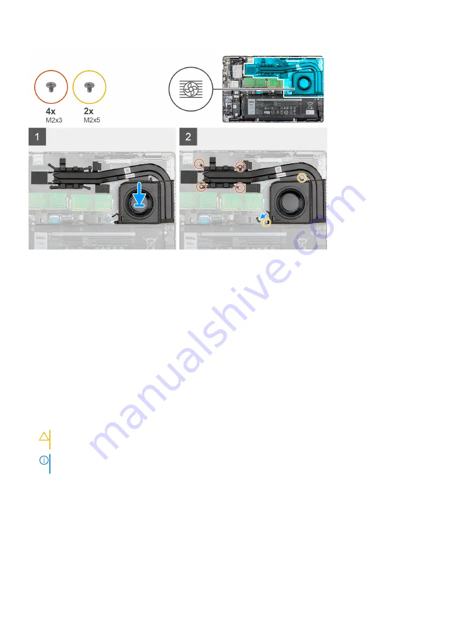
1. Align the screw holes on the heat sink and fan assembly with the screw holes on the system board.
2. In sequential order (as indicated on the heat sink), tighten the four (M2x3) and two (M2x5) screws that secure the heat sink
and fan assembly to the system board.
Next steps
1. Install the
2. Install the
.
3. Install the
.
4. Exit
.
After working inside your computer
.
Removing the heat sink and fan assembly - Discrete configuration
Prerequisites
Before working inside your computer
.
CAUTION:
For maximum cooling of the processor, do not touch the heat transfer areas on the heat sink. The
oils in your skin can reduce the heat transfer capability of the thermal grease.
NOTE:
The heat sink may become hot during normal operation. Allow sufficient time for the heat sink to cool before you
touch it.
2. Enter
.
3. Remove the
4. Remove the
.
5. Remove the
.
About this task
The following images indicate the location of the heat sink and fan assembly for a system with discrete configuration and
provide a visual representation of the removal procedure.
44
Removing and installing components
Summary of Contents for Inspiron 5421
Page 6: ...Chapter 6 Getting help 127 Contacting Dell 127 6 Contents ...
Page 14: ...Major components of your system 1 Base cover 14 Removing and installing components ...
Page 21: ...Removing and installing components 21 ...
Page 70: ...70 Removing and installing components ...
Page 72: ...72 Removing and installing components ...
Page 73: ...Removing and installing components 73 ...
Page 78: ...78 Removing and installing components ...
Page 79: ...Removing and installing components 79 ...
Page 82: ...82 Removing and installing components ...


