background image

Steps

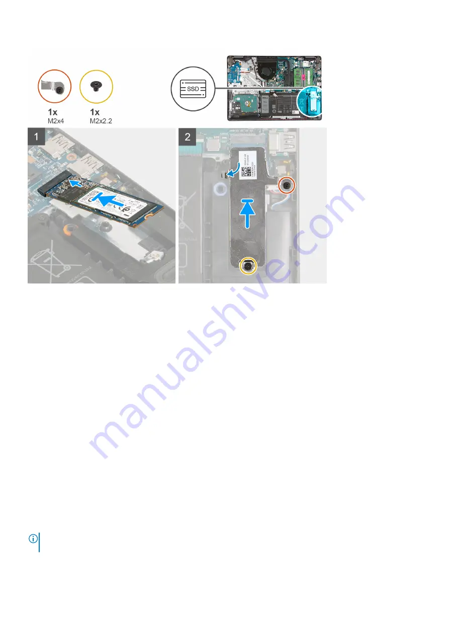
1. Align the notch on the M.2 2280 solid-state drive with the tab on the M.2 card slot on the system board.
2. Slide the M.2 2280 solid-state drive into the M.2 card slot on the system board.
3. Place the M.2 thermal shield on the M.2 2280 solid-state drive.
4. Align the screw holes on the M.2 thermal shield with the screw holes on the palm-rest and keyboard assembly.
5. Replace the screw (M2x2.2) that secures the M.2 thermal shield to the palm-rest and keyboard assembly.
6. Tighten the captive screw (M2x4) that secures the M.2 thermal shield to the palm-rest and keyboard assembly.

Next steps

1. Install the 

base cover

.

2. Follow the procedure in 

After working inside your computer

.

Memory module

Removing the memory module

Prerequisites

1. Follow the procedure in 

Before working inside your computer

.

2. Remove the 

base cover

.

About this task

NOTE:

 Depending on the configuration ordered your computer may come shipped with one or two memory module

installed.

The following images indicate the location of the memory module and provides a visual representation of the removal procedure.

20

Removing and installing components

Summary of Contents for Inspiron 3502

Page 1: ...Inspiron 3502 Service Manual Regulatory Model P90F Regulatory Type P90F003 August 2021 Rev A03 ...

Page 2: ...tial damage to hardware or loss of data and tells you how to avoid the problem WARNING A WARNING indicates a potential for property damage personal injury or death 2020 2021 Dell Inc or its subsidiaries All rights reserved Dell EMC and other trademarks are trademarks of Dell Inc or its subsidiaries Other trademarks may be trademarks of their respective owners ...

Page 3: ... solid state drive 17 Removing the M 2 2280 solid state drive 18 Installing the M 2 2280 solid state drive 19 Memory module 20 Removing the memory module 20 Installing the memory module 21 Wireless card 22 Removing the wireless card 22 Installing the wireless card 23 Battery 25 Lithium ion battery precautions 25 Removing the battery 25 Installing the battery 26 Hard drive 27 Removing the hard driv...

Page 4: ...ling the camera 50 Touchpad 51 Removing the touchpad 51 Installing the touchpad 52 System board 53 Removing the system board 53 Installing the system board 56 Power adapter port 58 Removing the power adapter port 58 Installing the power adapter port 59 Palm rest and keyboard assembly 60 Removing the palm rest and keyboard assembly 60 Installing the palm rest and keyboard assembly 61 Chapter 3 Driv...

Page 5: ...ng 73 Handling swollen Lithium ion batteries 73 Locate the Service Tag or Express Service Code of your Dell computer 73 System diagnostic lights 74 SupportAssist On board Diagnostics 75 Recovering the operating system 75 Backup media and recovery options 75 WiFi power cycle 75 Drain residual flea power perform hard reset 76 Chapter 6 Getting help and contacting Dell 77 Contents 5 ...

Page 6: ...r computer For more safety best practices see the Regulatory Compliance home page at www dell com regulatory_compliance WARNING Disconnect your computer from all power sources before opening the computer cover or panels After you finish working inside the computer replace all covers panels and screws before connecting your computer to an electrical outlet CAUTION To avoid damaging the computer ens...

Page 7: ...may cause degradation of memory integrity intermittent memory errors etc The more difficult type of damage to recognize and troubleshoot is the intermittent also called latent or walking wounded failure Perform the following steps to prevent ESD damage Use a wired ESD wrist strap that is properly grounded The use of wireless anti static straps is no longer allowed they do not provide adequate prot...

Page 8: ...y handling any hardware components ESD Packaging All ESD sensitive devices must be shipped and received in static safe packaging Metal static shielded bags are preferred However you should always return the damaged part using the same ESD bag and packaging that the new part arrived in The ESD bag should be folded over and taped shut and all the same foam packing material should be used in the orig...

Page 9: ...nt is replaced NOTE Some computers have magnetic surfaces Ensure that the screws are not left attached to such surfaces when replacing a component NOTE Screw color may vary with the configuration ordered Table 1 Screw list Component Secured to Screw type Quantity Screw image Base cover Palm rest and keyboard assembly M2 5x6 7 Base cover Palm rest and keyboard assembly Captive screw M2 5x2 5 5L 2 B...

Page 10: ...ssembly Captive screw 1 M 2 thermal shield Palm rest and keyboard assembly M2x2 2 1 M 2 2230 solid state drive Palm rest and keyboard assembly M2x2 1 System board Palm rest and keyboard assembly M2x4 1 Touchpad Palm rest and keyboard assembly M2x2 2 Touchpad bracket Palm rest and keyboard assembly M2x2 3 Wireless card bracket System board M2x3 1 Major components of Inspiron 3502 The following imag...

Page 11: ...ve if installed 6 System board 7 M 2 2230 solid state drive if installed 8 Memory module 9 Speakers 10 Palm rest and keyboard assembly 11 Touchpad 12 Display assembly 13 Power button with optional fingerprint reader 14 I O board 15 Coin cell battery Removing and installing components 11 ...

Page 12: ...epresentative for purchase options Base cover Removing the base cover Prerequisites 1 Follow the procedure in Before working inside your computer About this task NOTE Before removing the base cover ensure that there is no micro SD card installed in the micro SD card slot on your computer The following images indicate the location of the base cover and provides a visual representation of the remova...

Page 13: ...Removing and installing components 13 ...

Page 14: ...e base cover off the palm rest and keyboard assembly 5 Disconnect the battery cable from the system board and turn the computer over 6 Press and hold the power button for 15 seconds to ground the computer and drain the flea power Installing the base cover Prerequisites If you are replacing a component remove the existing component before performing the installation process About this task The foll...

Page 15: ...Removing and installing components 15 ...

Page 16: ... and keyboard assembly Next steps 1 Follow the procedure in After working inside your computer Solid state drive Removing the M 2 2230 solid state drive Prerequisites 1 Follow the procedure in Before working inside your computer 2 Remove the base cover About this task NOTE This procedure applies only to computers shipped with an M 2 2230 solid state drive installed NOTE The M 2 card installed on y...

Page 17: ...ate drive to the screw mount on the M 2 thermal shield 5 Lift the M 2 2230 solid state drive off the M 2 thermal shield Installing the M 2 2230 solid state drive Prerequisites If you are replacing a component remove the existing component before performing the installation process About this task NOTE This procedure applies if you are installing a M 2 2230 solid state drive NOTE The M 2 card insta...

Page 18: ...rd assembly 7 Replace the screw M2x2 2 that secures the M 2 thermal shield to the palm rest and keyboard assembly 8 Tighten the captive screw M2x4 that secures the M 2 thermal shield to the palm rest and keyboard assembly Next steps 1 Install the base cover 2 Follow the procedure in After working inside your computer Removing the M 2 2280 solid state drive Prerequisites 1 Follow the procedure in B...

Page 19: ...rive from the M 2 card slot on the system board Installing the M 2 2280 solid state drive Prerequisites If you are replacing a component remove the existing component before performing the installation process About this task NOTE This procedure applies if you are installing a M 2 2280 solid state drive NOTE The M 2 card installed on your computer will depend on the configuration ordered Supported...

Page 20: ...yboard assembly 6 Tighten the captive screw M2x4 that secures the M 2 thermal shield to the palm rest and keyboard assembly Next steps 1 Install the base cover 2 Follow the procedure in After working inside your computer Memory module Removing the memory module Prerequisites 1 Follow the procedure in Before working inside your computer 2 Remove the base cover About this task NOTE Depending on the ...

Page 21: ...stem board 3 Repeat the procedure above for the second memory module if applicable Installing the memory module Prerequisites If you are replacing a component remove the existing component before performing the installation process About this task The following images indicate the location of the memory module and provides a visual representation of the installation procedure Removing and installi...

Page 22: ...o place remove the memory module from the slot and repeat steps 1 to 3 5 Repeat the procedure above for the second memory module if applicable Next steps 1 Install the base cover 2 Follow the procedure in After working inside your computer Wireless card Removing the wireless card Prerequisites 1 Follow the procedure in Before working inside your computer 2 Remove the base cover About this task The...

Page 23: ... and remove the wireless card from the M 2 card slot on the system board Installing the wireless card Prerequisites If you are replacing a component remove the existing component before performing the installation process About this task The following images indicate the location of the wireless card and provides a visual representation of the installation procedure Removing and installing compone...

Page 24: ...s card Antenna cable color Main white triangle White Auxiliary black triangle Black 2 Slide the wireless card into the M 2 card slot on the system board 3 Place the wireless card bracket on the wireless card 4 Replace the screw M2x3 that secures the wireless card bracket to the system board Next steps 1 Install the base cover 2 Follow the procedure in After working inside your computer 24 Removing...

Page 25: ... prevent accidental puncture or damage to the battery and other system components If the battery gets stuck inside your computer as a result of swelling do not try to release it as puncturing bending or crushing a lithium ion battery can be dangerous In such an instance contact Dell technical support for assistance See www dell com contactdell Always purchase genuine batteries from www dell com or...

Page 26: ... lift the battery off the palm rest and keyboard assembly Installing the battery Prerequisites If you are replacing a component remove the existing component before performing the installation process About this task The following images indicate the location of the battery and provides a visual representation of the installation procedure 26 Removing and installing components ...

Page 27: ...est and keyboard assembly 4 Connect the battery cable to the connector on the system board Next steps 1 Install the base cover 2 Follow the procedure in After working inside your computer Hard drive Removing the hard drive Prerequisites 1 Follow the procedure in Before working inside your computer 2 Remove the base cover 3 Remove the battery About this task The following images indicate the locati...

Page 28: ...e from the hard drive 5 Remove the four screws M3x3 that secure the hard drive bracket to the hard drive 6 Slide and remove the hard drive bracket from the hard drive Installing the hard drive Prerequisites If you are replacing a component remove the existing component before performing the installation process About this task The following images indicate the location of the hard drive and provid...

Page 29: ...e hard drive assembly on the palm rest and keyboard assembly 6 Align the screw holes on the hard drive assembly to the screw holes on the palm rest and keyboard assembly 7 Replace the three screws M2x3 that secure the hard drive assembly to the palm rest and keyboard assembly 8 Connect the hard drive cable to the connector on the system board Next steps 1 Install the battery 2 Install the base cov...

Page 30: ...ct the fingerprint reader board cable from the I O board if applicable 2 Open the latch and disconnect the I O board power cable from the I O board 3 Open the latch and disconnect the fingerprint reader cable from the I O board if applicable 4 Open the latch and disconnect the I O board cable from the I O board 5 Remove the three screws M2x4 that secure the I O board to the palm rest and keyboard ...

Page 31: ...4 that secure the I O board to the palm rest and keyboard assembly NOTE When replacing the screws only replace the screws in the locations shown in the image 4 Connect the fingerprint reader board cable to the connector on the I O board and close the latch if applicable 5 Connect the I O board power cable to the connector on the I O board and close the latch 6 Connect the fingerprint reader cable ...

Page 32: ... 1 Flip the I O board over 2 Push on the securing clip to release the coin cell battery from its holder on the I O board 3 Lift the coin cell battery from its holder on the I O board Installing the coin cell battery Prerequisites If you are replacing a component remove the existing component before performing the installation process About this task The following images indicate the location of th...

Page 33: ...ase cover 3 Follow the procedure in After working inside your computer Speakers Removing the speakers Prerequisites 1 Follow the procedure in Before working inside your computer 2 Remove the base cover 3 Remove the M 2 2230 solid state drive if applicable 4 Remove the M 2 2280 solid state drive if applicable About this task The following images indicate the location of the speakers and provides a ...

Page 34: ...ith its cable off the palm rest and keyboard assembly Installing the speakers Prerequisites If you are replacing a component remove the existing component before performing the installation process About this task The following images indicate the location of the speakers and provides a visual representation of the installation procedure 34 Removing and installing components ...

Page 35: ... Follow the procedure in After working inside your computer Heat sink Removing the heat sink Prerequisites 1 Follow the procedure in Before working inside your computer 2 Remove the base cover About this task NOTE The heat sink may become hot during normal operation Allow sufficient time for the heat sink to cool before you touch it NOTE For maximum cooling of the processor do not touch the heat t...

Page 36: ...tem board or the heat sink is replaced use the thermal grease provided in the kit to ensure that thermal conductivity is achieved The following images indicate the location of the heat sink and provides a visual representation of the installation procedure Steps 1 Place the heat sink on the system board 2 Replace the two screws M2x5 that secure the heat sink to the palm rest and keyboard assembly ...

Page 37: ...t secure the power button with optional fingerprint reader to the palm rest and keyboard assembly 2 Open the latch and disconnect the power button cable from the fingerprint reader board if applicable NOTE This step is only applicable if your computer was shipped with the optional fingerprint reader 3 Peel the Mylar that secures and grounds the power button cable to the palm rest and keyboard asse...

Page 38: ...Replace the two screws M2x3 that secure the power button to the palm rest and keyboard assembly 3 Connect the power button cable to the fingerprint reader board and close the latch if applicable NOTE This step is only applicable if your computer was shipped with the optional fingerprint reader 4 Adhere the Mylar that secures and grounds the power button cable to the palm rest and keyboard assembly...

Page 39: ... Open the latch and disconnect the power button cable from the fingerprint reader board 2 Open the latch and disconnect the fingerprint reader board cable from the fingerprint reader board 3 Slide and remove the fingerprint reader board from the securing clip on the palm rest and keyboard assembly Installing the fingerprint reader board Prerequisites If you are replacing a component remove the exi...

Page 40: ...rd and close the latch Next steps 1 Install the base cover 2 Follow the procedure in After working inside your computer Display assembly Removing the display assembly Prerequisites 1 Follow the procedure in Before working inside your computer 2 Remove the base cover 3 Remove the wireless card About this task The following images indicate the location of the display assembly and provides a visual r...

Page 41: ...Removing and installing components 41 ...

Page 42: ...x screws M2 5x6 that secure the display hinges to the palm rest and keyboard assembly 5 Lift the display assembly from the palm rest and keyboard assembly Installing the display assembly Prerequisites If you are replacing a component remove the existing component before performing the installation process About this task The following images indicate the location of the display assembly and provid...

Page 43: ...ly 5 Connect the display cable to the connector on the system board Next steps 1 Install the wireless card 2 Install the base cover 3 Follow the procedure in After working inside your computer Display bezel Removing the display bezel Prerequisites 1 Follow the procedure in Before working inside your computer 2 Remove the base cover 3 Remove the wireless card 4 Remove the display assembly About thi...

Page 44: ...display assembly Installing the display bezel Prerequisites If you are replacing a component remove the existing component before performing the installation process About this task The following images indicate the location of the display bezel and provides a visual representation of the installation procedure 44 Removing and installing components ...

Page 45: ... bezel and snap the display bezel in place Next steps 1 Install the display assembly 2 Install the wireless card 3 Install the base cover 4 Follow the procedure in After working inside your computer Display panel Removing the display panel Prerequisites 1 Follow the procedure in Before working inside your computer 2 Remove the base cover 3 Remove the wireless card 4 Remove the display assembly Rem...

Page 46: ...Remove the display bezel About this task The following images indicate the location of the display panel and provides a visual representation of the removal procedure 46 Removing and installing components ...

Page 47: ...or latch to the display panel 6 Lift the display cable latch and disconect the display cable from the display panel 7 Lift the display panel off the display assembly NOTE The display brackets are shipped together with the display panel do not remove the display brackets from the display panel Installing the display panel Prerequisites If you are replacing a component remove the existing component ...

Page 48: ...48 Removing and installing components ...

Page 49: ...lay assembly 6 Replace the six screws M2 5x2 5 that secure the display panel to the display assembly 7 Replace the two screws M2x2 5 that secure the display panel to the display assembly Next steps 1 Install the display assembly 2 Install the wireless card 3 Install the base cover 4 Follow the procedure in After working inside your computer Camera Removing the camera Prerequisites 1 Follow the pro...

Page 50: ...plastic scribe pry the camera from the display assembly 3 Lift the camera off the display assembly Installing the camera Prerequisites If you are replacing a component remove the existing component before performing the installation process About this task The following images indicate the location of the camera and provides a visual representation of the installation procedure 50 Removing and ins...

Page 51: ...ess card 5 Install the base cover 6 Follow the procedure in After working inside your computer Touchpad Removing the touchpad Prerequisites 1 Follow the procedure in Before working inside your computer 2 Remove the base cover 3 Remove the battery About this task The following images indicate the location of the touchpad and provides a visual representation of the removal procedure Removing and ins...

Page 52: ...m rest and keyboard assembly 5 Peel the tape that secures the touchpad to the palm rest and keyboard assembly 6 Lift the touchpad off the palm rest and keyboard assembly Installing the touchpad Prerequisites If you are replacing a component remove the existing component before performing the installation process About this task The following images indicate the location of the touchpad and provide...

Page 53: ... the screw holes on the touchpad bracket to the screw holes on the palm rest and keyboard assembly 9 Replace the three screws M2x3 that secure the touchpad bracket to the palm rest and keyboard assembly 10 Connect the touchpad cable to the touchpad and close the latch Next steps 1 Install the battery 2 Install the base cover 3 Follow the procedure in After working inside your computer System board...

Page 54: ... 3 Keyboard cable 4 Keyboard backlight cable 5 Touchpad cable 6 Battery cable 7 Hard drive cable 8 I O board cable 9 Fingerprint reader cable 10 Power button cable The following images indicate the location of the system board and provide a visual representation of the removal procedure 54 Removing and installing components ...

Page 55: ...board if applicable 5 Open the latch and disconnect the touchpad cable from the system board 6 Open the latch and disconnect the keyboard backlight cable from the system board if applicable 7 Open the latch and disconnect the keyboard cable from the system board 8 Disconnect the speaker cable from the system board 9 Remove the screw M2x4 that secures the system board to the palm rest and keyboard ...

Page 56: ...nnectors on the system board 1 Power adapter port cable 2 Speaker cable 3 Keyboard cable 4 Keyboard backlight cable 5 Touchpad cable 6 Battery cable 7 Hard drive cable 8 I O board cable 9 Fingerprint reader cable 10 Power button cable The following images indicate the location of the system board and provides a visual representation of the installation procedure 56 Removing and installing componen...

Page 57: ...system board and close the latch 6 Connect the keyboard backlight cable to the connector on the system board and close the latch if applicable 7 Connect the touchpad cable to the connector on the system board and close the latch 8 Connect the hard drive cable to the connector on the system board and close the latch if applicable 9 Connect the I O board cable to the connector on the system board an...

Page 58: ...r adapter port Removing the power adapter port Prerequisites 1 Follow the procedure in Before working inside your computer 2 Remove the base cover 3 Remove the M 2 2230 solid state drive if applicable 4 Remove the M 2 2280 solid state drive if applicable 5 Remove the wireless card 6 Remove the display assembly 7 Remove the system board NOTE The system board can be removed along with the heat sink ...

Page 59: ...r port Prerequisites If you are replacing a component remove the existing component before performing the installation process About this task The following images indicate the location of the power adapter port and provides a visual representation of the installation procedure Removing and installing components 59 ...

Page 60: ... After working inside your computer Palm rest and keyboard assembly Removing the palm rest and keyboard assembly Prerequisites 1 Follow the procedure in Before working inside your computer 2 Remove the base cover 3 Remove the M 2 2230 solid state drive if applicable 4 Remove the M 2 2280 solid state drive if applicable 5 Remove the hard drive 6 Remove the wireless card 7 Remove the display assembl...

Page 61: ...epresentation of the removal procedure Steps After performing the pre requisites you are left with the palm rest and keyboard assembly Installing the palm rest and keyboard assembly Prerequisites If you are replacing a component remove the existing component before performing the installation process About this task The following images indicate the location of the palm rest and keyboard assembly ...

Page 62: ...optional fingerprint reader 4 Install the I O board 5 Install the speakers 6 Install the touchpad 7 Install the fingerprint reader board 8 Install the display assembly 9 Install the wireless card 10 Install the hard drive 11 Install the M 2 2230 solid state drive if applicable 12 Install the M 2 2280 solid state drive if applicable 13 Install the base cover 14 Follow the procedure in After working...

Page 63: ...rivers and downloads When troubleshooting downloading or installing drivers it is recommended that you read the Dell Knowledge Based article Drivers and Downloads FAQ 000123347 3 Drivers and downloads 63 ...

Page 64: ...ling base devices Entering BIOS setup program Steps 1 Turn on your computer 2 Press F2 immediately to enter the BIOS setup program NOTE If you wait too long and the operating system logo appears continue to wait until you see the desktop Then turn off your computer and try again Navigation keys NOTE For most of the System Setup options changes that you make are recorded but do not take effect unti...

Page 65: ...tion System Time Displays the current time in hh mm ss format System Date Displays the current date in mm dd yyyy format BIOS Version Displays the BIOS version Product Name Displays the model number of your computer Service Tag Displays the service tag of your computer Asset Tag Displays the asset tag of your computer CPU Type Displays the processor type CPU Speed Displays the processor speed CPU ...

Page 66: ...ation Enables you to configure the operating mode of the integrated SATA drive controller Choose one of the following options Disabled The SATA controllers are hidden AHCI SATA is configured for AHCI mode RAID On SATA is configured to support RAID mode Default AHCI Adapter Warnings Enables or disables the system setup BIOS warning messages when you use certain power adapters Enable Adapter Warning...

Page 67: ...ng power usage hours Use the below options to prevent AC power usage between certain times of each day Default Adaptive Battery settings are adaptively optimized based on your typical battery usage pattern Advanced Battery Charge Mode Enables or disables Advanced Battery Charge Configuration from the beginning of the day to a specified work period Advanced Battery Charged maximizes battery health ...

Page 68: ...lute Software Default Enabled Absolute status Displays the status of the Computrace Service from the Absolute Software Default Deactivate Firmware TPM Enables or disables the Trusted Platform Module TPM during POST Default Enabled PPI Bypass for Clear Command Enables you to control the TPM Physical Presence Interface PPI When enabled this setting will allow the OS to skip BIOS PPI user prompts whe...

Page 69: ... all system setup options Restore Defaults Enables you to restore default values for all system setup options Discard Changes Enables you to load previous values for all system setup options Save Changes Enables you to save the changes for all system setup options System and setup password Table 9 System and setup password Password type Description System password Password that you must enter to l...

Page 70: ...rd Prerequisites Ensure that the Password Status is Unlocked in the System Setup before attempting to delete or change the existing System and Admin password You cannot delete or change an existing System or Admin password if the Password Status is Locked About this task To enter the System Setup press F2 immediately after a power on or reboot Steps 1 In the System BIOS or System Setup screen sele...

Page 71: ... Expand Find drivers 4 Select the operating system installed on your computer 5 In the Category drop down list select BIOS 6 Select the latest version of BIOS and click Download to download the BIOS file for your computer 7 After the download is complete browse the folder where you saved the BIOS update file 8 Double click the BIOS update file icon and follow the on screen instructions For more in...

Page 72: ... following USB drive formatted to the FAT32 file system key does not have to be bootable BIOS executable file that you downloaded from the Dell Support website and copied to the root of the USB drive AC power adapter that is connected to the computer Functional computer battery to flash the BIOS Perform the following steps to perform the BIOS update flash process from the F12 menu CAUTION Do not t...

Page 73: ...cks and cells Do not apply pressure to the surface of the battery Do not bend the battery Do not use tools of any type to pry on or against the battery If a battery gets stuck in a device as a result of swelling do not try to free it as puncturing bending or crushing a battery can be dangerous Do not attempt to reassemble a damaged or swollen battery into a laptop Swollen batteries that are covere...

Page 74: ...The following diagnostic light codes and recommended solutions are intended for Dell service technicians to troubleshoot problems You should only perform troubleshooting and repairs as authorized or directed by the Dell technical support team Damage due to servicing that is not authorized by Dell is not covered by your warranty Table 10 Diagnostic light codes Diagnostic light codes Amber white Pro...

Page 75: ...st Pre Boot System Performance Check Recovering the operating system When your computer is unable to boot to the operating system even after repeated attempts it automatically starts Dell SupportAssist OS Recovery Dell SupportAssist OS Recovery is a standalone tool that is preinstalled in all Dell computers installed with Windows operating system It consists of tools to diagnose and troubleshoot i...

Page 76: ...or replacing any components in your computer Draining residual flea power also known as a performing a hard reset is also a common troubleshooting step if your computer does not power on or boot into the operating system To drain residual flea power perform a hard reset Steps 1 Turn off your computer 2 Disconnect the power adapter from your computer 3 Remove the base cover 4 Remove the battery 5 P...

Page 77: ...r Express Service Code at www dell com support For more information on how to find the Service Tag for your computer see Locate the Service Tag on your computer Dell knowledge base articles for a variety of computer concerns 1 Go to www dell com support 2 On the menu bar at the top of the Support page select Support Knowledge Base 3 In the Search field on the Knowledge Base page type the keyword t...

Reviews: