background image

Back to Contents Page


 Modem  

Dell™ Inspiron™ 1501 Service Manual


Removing the Modem 


Replacing the Modem 


Removing the Modem  


1.

Follow the instructions in 

Before You Begin

.  


2.

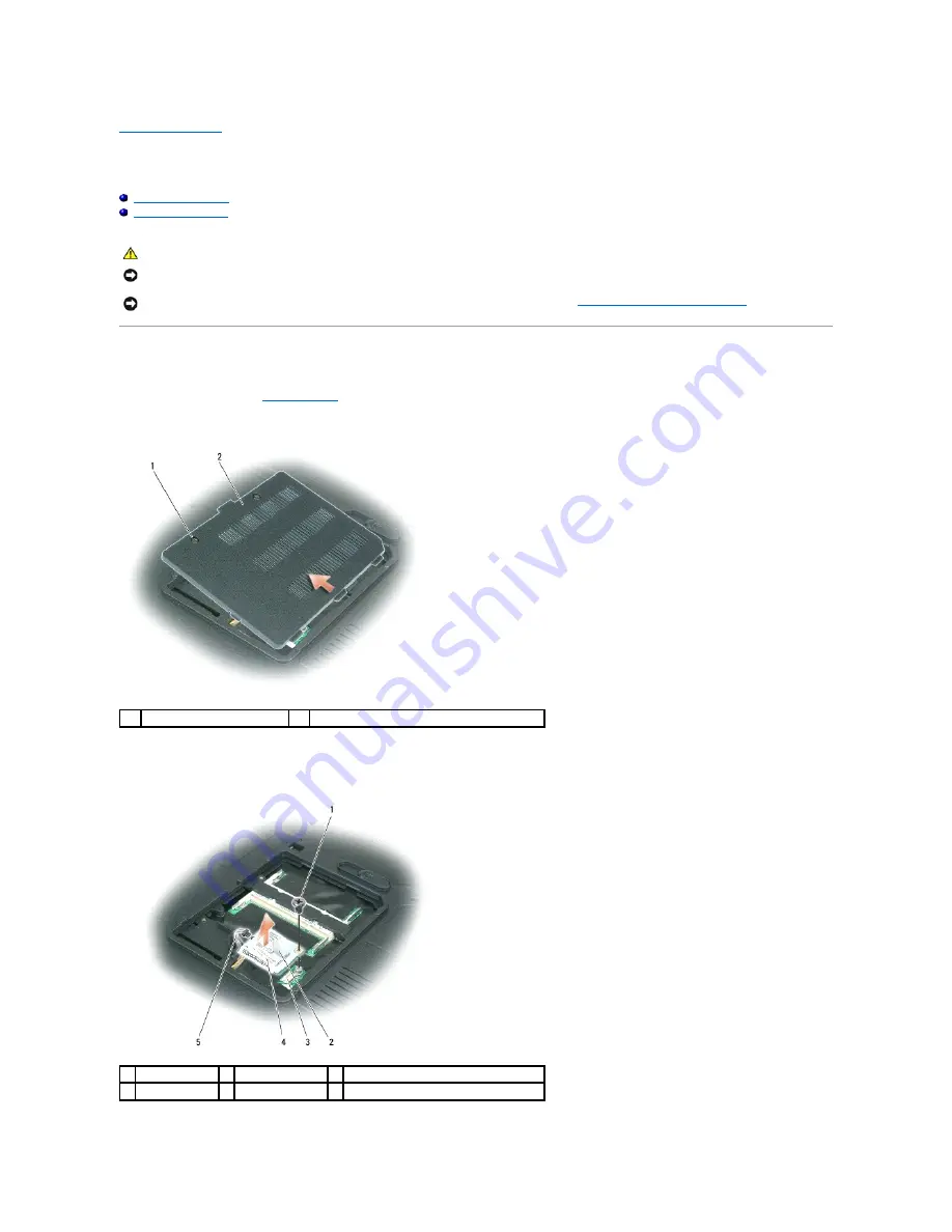
Turn the computer upside-down, loosen the two captive screws on the memory module/modem cover, and remove the cover from the computer.  


3.

Remove the M2 x 3-mm screw that attaches the modem to the system board.  


4.

Pull up on the pull-tab to disconnect the modem from the modem connector on the system board.  


CAUTION: 

Before you begin the following procedure, follow the safety instructions in the 

Product Information Guide

.


NOTICE: 

To avoid electrostatic discharge, ground yourself by using a wrist grounding strap or by periodically touching an unpainted metal surface (such 

as the back panel) on the computer.


NOTICE: 

To help prevent damage to the system board, you must remove the main battery (see 

Before Working Inside Your Computer

) before you 

begin working inside the computer. 

captive screws (2) 

memory module/modem cover 

1  modem screw 

2  modem pull-tab 

3  modem connector on system board 

4  modem 

5  modem cable 


Summary of Contents for Inspiron 1501 - Turion X2 TL-60 2GB DDR2

Page 1: ...emarks of Microsoft Corporation Other trademarks and trade names may be used in this document to refer to either the entities claiming the marks and names or their products Dell Inc disclaims any proprietary interest in trademarks and trade names other than its own Model PP23LA October 2006 Rev A00 Before You Begin Optical Drive Hard Drive Memory Module s Modem Mini Card Hinge Cover Keyboard Displ...

Page 2: ...em board see Removing the System Board 9 Remove the M2 x 2 7 mm screw from the battery latch assembly When you remove the M2 x 2 7 mm screw the battery latch release on the bottom of the computer will also be removed 10 Remove the spring from the hook on the computer base by lifting it away with a screwdriver or a plastic scribe CAUTION Before you begin the following procedure follow the safety in...

Page 3: ...e base and then replace the screw in the assembly Ensure that the newly installed latch moves smoothly and freely when pushed and released 4 Replace the system board see Replacing the System Board 5 Replace the processor thermal cooling assembly see Replacing the Processor Thermal Cooling Assembly 6 Replace the palm rest see Replacing the Palm Rest 7 Replace the display assembly see Replacing the ...

Page 4: ...rom potential damage and to help ensure your own personal safety 1 Ensure that the work surface is flat and clean to prevent the computer cover from being scratched 2 Turn off your computer see Turning Off Your Computer 3 Disconnect any telephone or network cables from the computer NOTICE To avoid losing data save and close any open files and exit any open programs before you turn off your compute...

Page 5: ...ter upside down on a flat work surface 6 Slide the battery bay latch release on the bottom of the computer 7 Remove the battery from the battery bay Back to Contents Page NOTICE To help prevent damage to the system board remove the main battery before working inside the computer 1 battery bay latch release 2 main battery ...

Page 6: ...BIOS When the flash update is complete the computer will automatically reboot 3 Press F2 during POST to enter the system setup program 4 Press Esc Suspend select Save changes and reboot and press Enter to save configuration changes 5 Remove the flash BIOS update program floppy or CD from the drive and restart the computer Back to Contents Page NOTE If you use a BIOS update program CD to flash the ...

Page 7: ...bly 9 Remove the assembly from the system board Replacing the ExpressCard Hard Drive Bay Assembly 1 At a 45 degree angle insert the end of the ExpressCard hard drive bay assembly into its access hole on the side of the computer base 2 Lower the assembly aligning the screw holes on the assembly with the holes on the system board 3 Replace the six M2 5x 5 mm screws from the assembly CAUTION Before y...

Page 8: ...Back to Contents Page ...

Page 9: ... tabs toward the back of the computer until the card pops up slightly 6 Lift the Mini Card out of its system board connector CAUTION Before you begin any of the procedures in this section follow the safety instructions in the Product Information Guide NOTICE To avoid electrostatic discharge ground yourself by using a wrist grounding strap or by periodically touching an unpainted metal surface such...

Page 10: ...th a black triangle and connect the white antenna cable to the connector labeled with a white triangle 1 system board connector 2 Mini Card 3 metal securing tabs 2 NOTICE The system board and Mini Card connectors are keyed to ensure correct insertion If you feel resistance check the connectors on the card and on the system board and realign the card NOTICE Make sure the antenna cables are not unde...

Page 11: ...Back to Contents Page 1 Mini Card 2 white antenna cable white triangle 3 black antenna cable black triangle ...

Page 12: ...ert it at a 30 degree angle under the clip with the positive identified by a plus symbol side up and then push it into place 2 Replace the keyboard see Replacing the Keyboard 3 Replace the hinge cover see Replacing the Hinge Cover Back to Contents Page CAUTION Before you begin the following procedure follow the safety instructions in the Product Information Guide NOTICE To avoid electrostatic disc...

Page 13: ...hing an unpainted metal surface such as the back panel on the computer NOTICE Do not touch the processor die Press and hold the processor down on the substrate on which the die is mounted while turning the cam screw to prevent intermittent contact between the cam screw and processor NOTICE To avoid damage to the processor hold the screwdriver so that it is perpendicular to the processor when turni...

Page 14: ... Hinge Cover Back to Contents Page NOTICE Ensure that the cam lock is in the fully open position before seating the processor module Seating the processor module properly in the ZIF socket does not require force NOTICE A processor module that is not properly seated can result in an intermittent connection or permanent damage to the processor and ZIF socket NOTE If you have ordered a new microproce...

Page 15: ...crews labeled 1 through 4 in consecutive order Back to Contents Page CAUTION Before you begin the following procedure follow the safety instructions in the Product Information Guide NOTICE To avoid electrostatic discharge ground yourself by using a wrist grounding strap or by periodically touching an unpainted metal surface such as the back panel on the computer NOTICE To help prevent damage to th...

Page 16: ...he two M2 5 x 5 mm screws on the display hinge 9 Disconnect the antenna cables from the Mini Card and dislodge the cables from the antenna cable channel 10 Loosen the captive screw on the grounding wire and dislodge the display cable from the display cable channel 11 Pull the pull tab straight up to disconnect the display cable from the system board CAUTION Before you begin the following procedure...

Page 17: ...inge Cover 8 Close the display 9 Replace the two M2 5 x 8 mm screws in the back of the computer and replace the two screw covers 10 Turn the computer over and replace the two M2 5 x 8 mm screws in the bottom of the computer Display Bezel 1 M2 5 x 5 mm screws 2 2 display cable 3 display cable pull tab 4 captive screw 5 antenna cables 2 6 antenna cable channel 7 standby switch 8 display cable connec...

Page 18: ...1 Starting at any corner use your fingers to gently snap the bezel into place to secure it to the display assembly 2 Replace the six M2 5 x 4 2 mm screws around the display bezel NOTICE To avoid electrostatic discharge ground yourself by using a wrist grounding strap or by periodically touching an unpainted metal surface such as the back panel on the computer NOTICE To help prevent damage to the s...

Page 19: ...ex cable connector away from the display connector 7 Pull straight up on the pull tab to disconnect the bottom flex cable connector from the inverter connector CAUTION Before you begin the following procedure follow the safety instructions in the Product Information Guide NOTICE To avoid electrostatic discharge ground yourself by using a wrist grounding strap or by touching an unpainted metal surf...

Page 20: ...Slide the latch to the right and gently lift 5 Remove the spring that attaches the latch to the display panel Replacing the Display Latch 1 pull tab on bottom flex cable connector 2 top flex cable connector 3 top display cable connector 4 inverter connector NOTE The eight screw locations are numbered Replace the screws in sequential order CAUTION Before you begin the following procedure follow the...

Page 21: ...1 Replace the spring that attaches the latch to the display panel 2 Align the latch with the display panel and slide the latch to the left to secure it into place Back to Contents Page ...

Page 22: ...nnect the fan connector from the connector on the system board Back to Contents Page CAUTION Before you begin the following procedure follow the safety instructions in the Product Information Guide NOTICE To avoid electrostatic discharge ground yourself by using a wrist grounding strap or by periodically touching an unpainted metal surface such as the back panel on the computer NOTICE To help prev...

Page 23: ...uch the metal housing of the hard drive CAUTION Before you begin the following procedure follow the safety instructions in the Product Information Guide NOTICE To help prevent damage to the system board remove the main battery see Before Working Inside Your Computer before working inside the computer NOTICE To prevent data loss turn off your computer before removing the hard drive Do not remove th...

Page 24: ...Back to Contents Page ...

Page 25: ...ck into place starting from left to right Back to Contents Page CAUTION Before you begin the following procedure follow the safety instructions in the Product Information Guide NOTICE To avoid electrostatic discharge ground yourself by using a wrist grounding strap or by periodically touching an unpainted metal surface such as the back panel on the computer NOTICE To help prevent damage to the sys...

Page 26: ...the computer slide the keyboard cable into the connector on the system board and close the connector latch 2 Slide the tabs on the keyboard under the palm rest CAUTION Before you begin the following procedure follow the safety instructions in the Product Information Guide NOTICE To avoid electrostatic discharge ground yourself by using a wrist grounding strap or by periodically touching an unpaint...

Page 27: ...3 Press lightly on the top edges of the keyboard to snap it into place 4 Replace the two M2 5 x 5 mm screws at the top of the keyboard Back to Contents Page ...

Page 28: ...ide your computer discharge static electricity from your body before you touch any of your computer s electronic components You can do so by touching an unpainted metal surface NOTICE To help prevent damage to the system board you must remove the main battery see Before Working Inside Your Computer before you begin working inside the computer NOTE Memory modules purchased from Dell are covered und...

Page 29: ...matically updates the system configuration information Back to Contents Page 1 memory module 2 securing clips 2 NOTICE To prevent static damage to components inside your computer discharge static electricity from your body before you touch any of your computer s electronic components You can do so by touching an unpainted metal surface NOTE To get maximum performance dual channel memory bandwidth ...

Page 30: ...modem connector on the system board CAUTION Before you begin the following procedure follow the safety instructions in the Product Information Guide NOTICE To avoid electrostatic discharge ground yourself by using a wrist grounding strap or by periodically touching an unpainted metal surface such as the back panel on the computer NOTICE To help prevent damage to the system board you must remove th...

Page 31: ...ector on the bottom of the modem with the modem connector on the system board and press down on the right side of the modem 3 Replace the M2 x 3 mm screw Back to Contents Page NOTICE Do not disconnect the modem cable from the system board NOTICE Ensure that the modem cable is routed correctly when you replace the modem ...

Page 32: ...ase the optical drive from the media bay 4 Pull the drive out of the media bay Back to Contents Page CAUTION Before you begin any of the procedures in this section follow the safety instructions in the Product Information Guide NOTICE To help prevent damage to drives store them in a safe dry place when they are not installed in the computer Avoid pressing down on them or placing heavy objects on t...

Page 33: ...the computer 7 Turn the computer top side up and loosen the captive screw on the palm rest 8 Disconnect the touch pad connector and the standby switch connector from the system board CAUTION Before you begin the following procedure follow the safety instructions in the Product Information Guide NOTICE To avoid electrostatic discharge ground yourself by using a wrist grounding strap or by periodica...

Page 34: ...9 Lift the palm rest and remove it from the computer Back to Contents Page 1 captive screw 2 standby switch connector 3 touch pad connector ...

Page 35: ...vice Manual USB Connector Video Connector USB Connector Video Connector Back to Contents Page Pin Signal 1 USB5V 2 USBP 3 USBP 4 GND Pin Signal Pin Signal 1 CRT_R 9 5V 2 CRT_G 10 GND 3 CRT_B 11 MONITOR_DETECT 4 NC 12 DDC_DATA 5 GND 13 CRT_HS 6 GND 14 CRT_VS 7 GND 15 DDC_CLK 8 GND ...

Page 36: ... from the speakers 8 Remove the speaker cable from the routing clips and remove the speakers CAUTION Before you begin the following procedure follow the safety instructions in the Product Information Guide NOTICE To avoid electrostatic discharge ground yourself by using a wrist grounding strap or by periodically touching an unpainted metal surface such as the back panel on the computer NOTICE To h...

Page 37: ...Back to Contents Page 1 cable routing clip 2 speaker cable ...

Page 38: ...9 Remove the display assembly see Removing the Display Assembly 10 Remove the palm rest see Removing the Palm Rest 11 Remove the fan see Removing a Fan 12 Remove the processor thermal cooling assembly see Removing the Processor Thermal Cooling Assembly 13 Remove the processor see Removing the Processor Module 14 Remove the ExpressCard hard drive bay assembly see Removing the ExpressCard Hard Drive...

Page 39: ...o screws in the back of the computer 4 Replace the ExpressCard hard drive bay assembly see Replacing the ExpressCard Hard Drive Bay Assembly 5 Replace the processor see Replacing the Processor Module 6 Replace the processor thermal cooling assembly see Replacing the Processor Thermal Cooling Assembly 7 Replace the fan see Replacing a Fan 8 Replace the palm rest see Replacing the Palm Rest 9 Replac...

Page 40: ...ons that appear on the screen See Flashing the BIOS for further information 20 Enter the system setup program to update the BIOS on the new system board with the computer Service Tag Back to Contents Page NOTICE Before turning on the computer replace all screws and ensure that no stray screws remain inside the computer Failure to do so may result in damage to the computer NOTE If you use a BIOS up...

Reviews: