background image

Steps

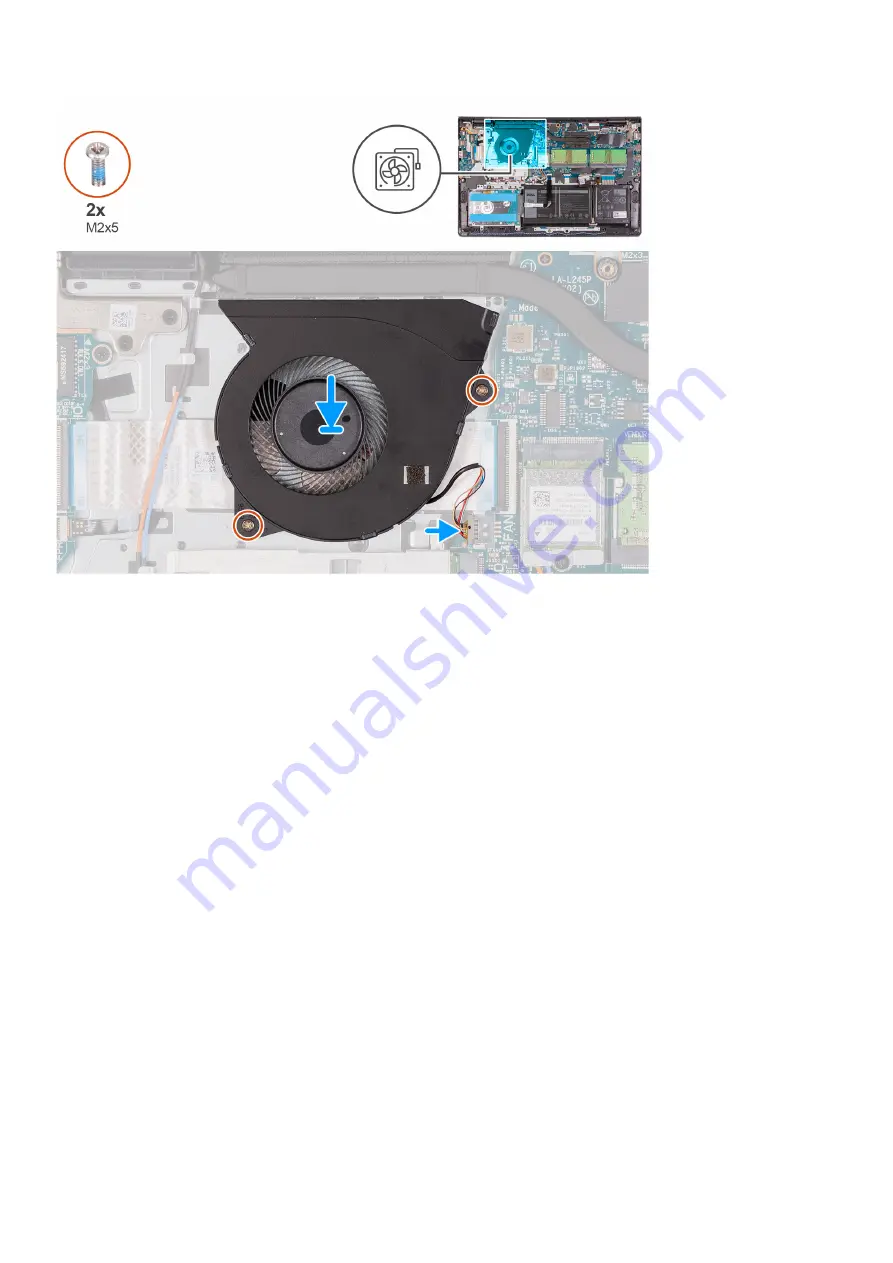
1. Align and place the fan on the palm-rest and keyboard assembly.
2. Replace the two screws (M2x5) to secure the fan to the palm-rest and keyboard assembly.
3. Connect the fan cable to the connector on the system board .

Next steps

1. Replace the 

base cover

.

2. Exit 

service mode

.

3. Replace the 

SD card

.

4. Follow the procedure in 

after working inside your computer

.

Heat sink

Removing the heat sink - UMA

Prerequisites

1. Follow the procedure in 

before working inside your computer

.

2. Remove the 

SD card

.

3. Enter 

service mode

.

4. Remove the 

base cover

.

About this task

The following images indicate the location of the heat sink and provides a visual representation of the removal procedure.

Removing and installing components

39

Summary of Contents for Inspiron 15 3510

Page 1: ...Vostro 15 3510 Service Manual Regulatory Model P112F Regulatory Type P112F001 P112F002 P112F003 June 2021 Rev A00 ...

Page 2: ...ential damage to hardware or loss of data and tells you how to avoid the problem WARNING A WARNING indicates a potential for property damage personal injury or death 2021 Dell Inc or its subsidiaries All rights reserved Dell EMC and other trademarks are trademarks of Dell Inc or its subsidiaries Other trademarks may be trademarks of their respective owners ...

Page 3: ...talling the base cover 20 Battery 21 Lithium ion battery precautions 21 Removing the 3 cell battery 21 Installing the 3 cell battery 22 Removing the 4 cell battery 23 Installing the 4 cell battery 24 Disconnecting the battery cable 25 Disconnecting the battery 26 Memory modules 27 Removing the memory module 27 Installing the memory module 28 WLAN card 29 Removing the WLAN card 29 Installing the WL...

Page 4: ...the display bezel 57 Installing the display bezel 58 Hinges 59 Removing the hinges 59 Installing the hinges 61 Display panel 62 Removing the display panel 62 Installation display panel 64 Camera 66 Removing the camera 66 Installing the camera 67 Display eDP cable 67 Removing the eDP cable 67 Installing the eDP cable 68 Display back cover 70 Removing the display back cover 70 Installing the display...

Page 5: ...7 System Management 98 Keyboard 98 Pre boot Behavior 99 Virtualization 100 Performance 101 System Logs 102 Updating the BIOS in Windows 102 Updating BIOS on systems with BitLocker enabled 103 Updating your system BIOS using a USB flash drive 103 Updating the BIOS in Linux and Ubuntu 104 Updating the BIOS from the F12 One Time boot menu 104 System and setup password 104 Assigning a system setup pas...

Page 6: ...WiFi power cycle 109 M BIST 110 Real Time Clock RTC reset 110 Handling swollen Lithium ion batteries 111 Chapter 6 Getting help and contacting Dell 112 6 Contents ...

Page 7: ...or at www dell com regulatory_compliance CAUTION Before touching anything inside your computer ground yourself by touching an unpainted metal surface such as the metal at the back of the computer While you work periodically touch an unpainted metal surface to dissipate static electricity which could harm internal components CAUTION When you disconnect a cable pull it by its connector or its pull t...

Page 8: ...and never to a painted or non metal surface The wrist strap should be secure and in full contact with your skin and ensure that you remove all jewelry such as watches bracelets or rings prior to bonding yourself and the equipment Electrostatic discharge ESD protection ESD is a major concern when you handle electronic components especially sensitive components such as expansion cards processors mem...

Page 9: ...t once per week A wrist strap tester is the best method for doing this test If you do not have your own wrist strap tester check with your regional office to find out if they have one To perform the test plug the wrist strap s bonding wire into the tester while it is strapped to your wrist and push the button to test A green LED is lit if the test is successful a red LED is lit and an alarm sounds...

Page 10: ...wn immediately Once the computer shuts down you may perform the replacement procedures without disconnecting the battery cable from the system board Exiting Service Mode Service Mode allows users to immediately cut off electricity from the computer and conduct repairs without disconnecting the battery cable from the system board To exit Service Mode 1 Connect the AC adapter to the power adapter po...

Page 11: ...ools Phillips 0 screwdriver Phillips 1 screwdriver Plastic scribe Recommended for field technician Screw List The following table shows the screw list and the images for different components Table 1 Screw Size List Component Screw type Quantity Image Base cover M2x5 Captive screw 6 2 Battery 3 cell M2x3 3 Battery 4 cell M2x3 4 WLAN M2x3 1 M 2 2230 SSD M2x2 1 M 2 2280 SSD M2x2 1 2 Removing and inst...

Page 12: ...Hard drive M2x3 4 Hard Drive Bracket M3x3 4 Touchpad M2x2 2 Touchpad bracket M2x2 3 System fan M2x5 2 Heatsink Integrated graphics M2x3 4 Heatsink Discrete graphics M2x3 7 System board M2 5x5 M2x3 M2x2 2 3 1 Power button M2x2 M2 5x5 2 12 Removing and installing components ...

Page 13: ...ponent Screw type Quantity Image I O board M2x3 3 Display assembly M2 5x5 4 Display hinge M2 5x3 8 6 Major components of Vostro 15 3510 The following image shows the major components of Vostro 15 3510 Removing and installing components 13 ...

Page 14: ...1 Base cover 2 Battery 3 Speaker 4 Power button with optional fingerprint reader 14 Removing and installing components ...

Page 15: ...1 Display assembly 12 Memory modules 13 WLAN card 14 IO daughter board 15 System board 16 Heatsink 17 System fan 18 IO daughter board FFC 19 Hard drive assembly Secure Digital Card Removing the Secure Digital card Prerequisites 1 Follow the procedure in Before working inside your computer Removing and installing components 15 ...

Page 16: ...About this task Steps 1 Push the secure digital card to release it from the computer 2 Slide the secure digital card out of the computer 16 Removing and installing components ...

Page 17: ...alling the Secure Digital card Prerequisites If you are replacing a component remove the existing component before performing the installation procedure About this task Removing and installing components 17 ...

Page 18: ...xt steps 1 Follow the procedure in after working inside your computer Base cover Removing the base cover Prerequisites 1 Follow the procedure in before working inside your computer 2 Remove the SD card 3 Enter service mode About this task 18 Removing and installing components ...

Page 19: ...tive screws that secure the base cover to the palm rest and keyboard assembly 3 Pry open the base cover starting from the recesses located in the U shaped indents at the top edge of the base cover near the hinges 4 Lift and slide the base cover off the palm rest and keyboard assembly Removing and installing components 19 ...

Page 20: ...Installing the base cover Prerequisites If you are replacing a component remove the existing component before performing the installation procedure About this task 20 Removing and installing components ...

Page 21: ...sure to the surface of the battery Do not bend the battery Do not use tools of any kind to pry on or against the battery Ensure any screws during the servicing of this product are not lost or misplaced to prevent accidental puncture or damage to the battery and other system components If the battery gets stuck inside your computer as a result of swelling do not try to release it as puncturing bend...

Page 22: ... and keyboard assembly 4 Lift and move the battery away from the computer Installing the 3 cell battery Prerequisites If you are replacing a component remove the existing component before performing the installation process About this task The following images indicate the location of the battery and provides a visual representation of the installation procedure 22 Removing and installing componen...

Page 23: ...Connect the battery cable to the connector on the system board Next steps 1 Install the base cover 2 Install the SD card 3 Follow the procedure in after working inside your computer Removing the 4 cell battery Prerequisites 1 Follow the procedure in before working inside your computer 2 Remove the SD card 3 Remove the base cover About this task The following images indicate the location of the bat...

Page 24: ...the battery away from the computer Installing the 4 cell battery Prerequisites If you are replacing a component remove the existing component before performing the installation process About this task The following images indicate the location of the battery and provides a visual representation of the installation procedure 24 Removing and installing components ...

Page 25: ...ry to the palmrest and keyboard assembly 4 Connect the battery cable to the connector on the system board Next steps 1 Install the base cover 2 Install the SD card 3 Follow the procedure in after working inside your computer Disconnecting the battery cable Prerequisites 1 Follow the procedure in before working inside your computer 2 Remove the SD card 3 Remove the base cover Removing and installin...

Page 26: ...cable 2 Disconnect the battery cable from the connector on the battery Disconnecting the battery Prerequisites 1 Follow the procedure in before working inside your computer 2 Remove the SD card 3 Remove the base cover 26 Removing and installing components ...

Page 27: ...ollow the procedure in before working inside your computer 2 Remove the SD card 3 Enter service mode 4 Remove the base cover About this task The following images indicate the location of the memory module and provides a visual representation of the removal procedure NOTE Depending on the configuration ordered your computer may come shipped with one or two memory module installed Removing and insta...

Page 28: ...tem board 3 Repeat the procedure above for the second memory module if applicable Installing the memory module Prerequisites If you are replacing a component remove the existing component before performing the installation procedure About this task The following images indicate the location of the memory module and provides a visual representation of the installation procedure 28 Removing and inst...

Page 29: ...E If the securing clips are not locking the memory module into place remove the memory module from the slot and repeat steps 1 and 2 4 Repeat the procedure above for the second memory module if applicable Next steps 1 Install the base cover 2 Exit service mode 3 Install the SD card 4 Follow the procedure in after working inside your computer WLAN card Removing the WLAN card Prerequisites 1 Follow ...

Page 30: ...ntenna cables 3 Disconnect the WLAN antenna cables from the connectors on the WLAN card 4 Slide and remove the wireless card from the M 2 card slot on the system board Installing the WLAN card Prerequisites If you are replacing a component remove the existing component before performing the installation procedure About this task The following images indicate the location of the wireless card and p...

Page 31: ... triangle White Auxiliary black triangle Black 2 Slide the wireless card into the M 2 card slot on the system board 3 Place the wireless card bracket on the wireless card 4 Replace the single M2x3 screw to secure the wireless card bracket and the wireless card to the system board Next steps 1 Install the base cover 2 Exit service mode 3 Install the SD card 4 Follow the procedure in after working i...

Page 32: ...s the thermal plate to the palm rest and keyboard assembly 2 Lift the M 2 2230 solid state drive thermal pate from over the M 2 2230 solid state drive 3 Slide and remove the M 2 2230 solid state drive from the M 2 card slot on the system board Installing the M 2 2230 solid state drive Prerequisites If you are replacing a component remove the existing component before performing the installation pr...

Page 33: ...lm rest and keyboard assembly 5 Replace the screw M2x2 that secures the thermal plate to the palm rest and keyboard assembly Next steps 1 Install the base cover 2 Exit service mode 3 Install the SD card 4 Follow the procedure in after working inside your computer Removing the M 2 2280 solid state drive Prerequisites 1 Follow the procedure in before working inside your computer 2 Remove the SD card...

Page 34: ... drive from the M 2 card slot on the system board Installing the M 2 2280 solid state drive Prerequisites If you are replacing a component remove the existing component before performing the installation procedure About this task The following images indicate the location of the M 2 2280 solid state drive and provides a visual representation of the installation procedure 34 Removing and installing...

Page 35: ... the screw M2x2 that secures the thermal plate to the palm rest and keyboard assembly Next steps 1 Install the base cover 2 Exit service mode 3 Install the SD card 4 Follow the procedure in after working inside your computer Hard drive Removing the hard drive Prerequisites 1 Follow the procedure in before working inside your computer 2 Remove the SD card 3 Enter service mode 4 Remove the base cove...

Page 36: ...nect the interposer from the hard drive 5 Remove the four M3x3 screws from the hard drive bracket 6 Slide and remove the hard drive bracket from the hard drive Installing the hard drive Prerequisites If you are replacing a component remove the existing component before performing the installation procedure About this task The following images indicate the location of the hard drive and provides a ...

Page 37: ...ve assembly on to the palm rest and keyboard assembly 5 Replace the four M2x3 screws to secure the hard drive assembly to the palm rest 6 Connect the hard drive cable to the system board and close the latch to secure the cable Next steps 1 Install the battery 2 Install the base cover 3 Exit service mode 4 Install the SD card 5 Follow the procedure in after working inside your computer Removing and...

Page 38: ...Disconnect the fan cable from the connector on the system board 2 Remove the two screws M2x5 that secures the fan to the palm rest and keyboard assembly 3 Lift and remove the fan from the computer Installing the system fan Prerequisites If you are replacing a component remove the existing component before performing the installation procedure About this task The following images indicate the locat...

Page 39: ...2 Exit service mode 3 Replace the SD card 4 Follow the procedure in after working inside your computer Heat sink Removing the heat sink UMA Prerequisites 1 Follow the procedure in before working inside your computer 2 Remove the SD card 3 Enter service mode 4 Remove the base cover About this task The following images indicate the location of the heat sink and provides a visual representation of th...

Page 40: ...nstalling the heat sink UMA Prerequisites If you are replacing a component remove the existing component before performing the installation procedure About this task The following images indicate the location of the heat sink and provides a visual representation of the installation procedure 40 Removing and installing components ...

Page 41: ...service mode 3 Install the SD card 4 Follow the procedure in after working inside your computer Removing the heat sink Discrete Prerequisites 1 Follow the procedure in before working inside your computer 2 Remove the SD card 3 Enter service mode 4 Remove the base cover About this task The following images indicate the location of the discrete heat sink and provides a visual representation of the r...

Page 42: ...g the heat sink Discrete Prerequisites If you are replacing a component remove the existing component before performing the installation procedure About this task The following images indicate the location of the discrete heat sink and provides a visual representation of the installation procedure 42 Removing and installing components ...

Page 43: ... mode 3 Install the SD card 4 Follow the procedure in after working inside your computer Speakers Removing the speakers Prerequisites 1 Follow the procedure in before working inside your computer 2 Remove the SD card 3 Enter service mode 4 Remove the base cover About this task The following images indicate the location of the speakers and provides a visual representation of the removal procedure R...

Page 44: ...e speakers Prerequisites If you are replacing a component remove the existing component before performing the installation procedure About this task The following images indicate the location of the speakers and provides a visual representation of the installation procedure NOTE If the rubber grommets are pushed out when removing the speakers push them back in before replacing the speakers 44 Remo...

Page 45: ...xt steps 1 Install the base cover 2 Exit service mode 3 Install the SD card 4 Follow the procedure in after working inside your computer IO board Removing the I O board Prerequisites 1 Follow the procedure in before working inside your computer 2 Remove the SD card 3 Enter service mode 4 Remove the base cover About this task The following images indicate the location of the I O board and provides ...

Page 46: ...e I O board from the system 4 Remove the three M2x3 screws that secure the I O board to the palm rest and keyboard assembly and remove the I O board from the system Installing the I O board Prerequisites If you are replacing a component remove the existing component before performing the installation procedure About this task The following images indicate the location of the I O board and provides...

Page 47: ... the latch if applicable 5 Connect the I O board power cable to the connector on the I O board and close the latch Next steps 1 Install the base cover 2 Exit service mode 3 Install the SD card 4 Follow the procedure in after working inside your computer Touchpad Removing the touchpad assembly Prerequisites 1 Follow the procedure in before working inside your computer 2 Remove the SD card 3 Remove ...

Page 48: ...embly 5 Diconnect the touchpad FFC from the system board 6 Remove the touchpad module with touchpad FFC from the computer Installing the touch pad assembly About this task The following images indicate the location of the touchpad and provides a visual representation of the installation procedure NOTE Ensure that the touch pad is aligned with the guides available on the palm rest and keyboard asse...

Page 49: ...d module to the palm rest and keyboard assembly 4 Install the touchpad bracket on the touchpad and secure it using the three M2x2 screws 5 Reconnect the hard drive FFC to the system board Next steps 1 Install the battery 2 Install the base cover 3 Install the SD card 4 Follow the procedure in after working inside your computer Removing and installing components 49 ...

Page 50: ...rking inside your computer 2 Remove the SD card 3 Enter service mode 4 Remove the base cover 5 Remove the WLAN card About this task The following images indicate the location of the display assembly and provides a visual representation of the removal procedure 50 Removing and installing components ...

Page 51: ...s 1 Disconnect the display cable from the connector on the system board 2 Unroute the WLAN antenna cables and the speaker cables from the routing guides on the computer Removing and installing components 51 ...

Page 52: ...bly at an angle to free it from the hinges and remove it from the display assembly Installing the display assembly Prerequisites If you are replacing a component remove the existing component before performing the installation procedure About this task NOTE Ensure that the hinges are opened to the maximum before replacing the display assembly on the palmrest and keyboard assembly 52 Removing and i...

Page 53: ...Steps 1 Align and place the system under the hinges on the display assembly 2 Fold the hinges back and install the four M2 5x5 screws to secure the display assembly Removing and installing components 53 ...

Page 54: ...low the procedure in after working inside your computer Hinge caps Removing the hinge caps Prerequisites 1 Follow the procedure in Before working inside your computer 2 Remove the SD card 3 Enter service mode 4 Remove the base cover 5 Remove the WLAN card 6 Remove the display assembly About this task The following images indicate the location of the hinge caps and provides a visual representation ...

Page 55: ... hinge cap in the center 5 Use the scribe to pry open the right hinge cap from the openings on itsinner side 6 Lift the inner side of the right hinge cap and remove it from the right hinge Installing the hinge caps Prerequisites If you are replacing a component remove the existing component before performing the installation procedure About this task The following images indicate the location of t...

Page 56: ...ib inside the right hinge cap to the outer sides 4 Push the right hinge cap down until it clicks in place Next steps 1 Install the display assembly 2 Install the WLAN card 3 Install the base cover 4 Exit service mode 5 Install the SD card 6 Follow the procedure in after working inside your computer 56 Removing and installing components ...

Page 57: ...he removal procedure Steps 1 Use a plastic scribe to pry open the display bezel from the outer edge at the left and right sides of the display hinges NOTE The display bezel is adhered to the display panel with adhesive Insert a plastic scribe into the recesses near both hinge caps to start the prying process to release the display bezel Pry along the outside edge of the display bezel and work your...

Page 58: ...e display bezel from the display assembly 4 Lift and remove the display bezel from the display assembly Installing the display bezel Prerequisites If you are replacing a component remove the existing component before performing the installation procedure About this task The following images indicate the location of the display bezel and provides a visual representation of the installation procedur...

Page 59: ...ly 4 Press down on the display bezel and snap the display bezel in place Next steps 1 Install the display assembly 2 Install the base cover 3 Exit service mode 4 Install the SD card 5 Follow the procedure in after working inside your computer Hinges Removing the hinges Prerequisites 1 Follow the procedure in Before working inside your computer 2 Remove the SD card Removing and installing component...

Page 60: ...ing images indicate the location of the hinge caps and provides a visual representation of the installation procedure Steps 1 Remove the three M2 5x3 8 from the left hinge 2 Lift and remove the left hinge from the display assembly 3 Remove the three M2 5x3 8 from the right hinge 4 Lift and remove the right hinge from the display assembly 60 Removing and installing components ...

Page 61: ... installation procedure Steps 1 Align and place the left hinge on the display assembly 2 Install the three M2 5x3 8 screws to secure the hinge to the display panel and back cover 3 Align and place the right hinge on the display assembly 4 Install the three M2 5x3 8 screws to secure the hinge to the display panel and back cover Next steps 1 Install the display bezel 2 Install the hinge caps 3 Insta...

Page 62: ... Follow the procedure in before working inside your computer 2 Remove the SD card 3 Enter service mode 4 Remove the base cover 5 Remove the WLAN card 6 Remove the display assembly 7 Remove the hinge caps 8 Remove the display bezel About this task The following images indicate the location of the display panel and provides a visual representation of the removal procedure 62 Removing and installing ...

Page 63: ...he display back cover using your hands 3 Lift the bottom side of the display panel and slide it downward to release the display brackets from the slots at the top side of the display cover 4 Gently flip the display panel assembly forward peel back the Mylar tape securing the display cable on the rear of the display panel Removing and installing components 63 ...

Page 64: ...system NOTE Do not remove the metal brackets from the panel Installation display panel Prerequisites If you are replacing a component remove the existing component before performing the installation procedure About this task The following images indicate the location of the display panel and provides a visual representation of the installation procedure 64 Removing and installing components ...

Page 65: ...that secures the display cable to the back of the display panel 4 Turn the display panel over and place it on the display back cover 5 Lift the bottom side of the display panel and slide the top side into the slots at the top of the display back cover 6 Gently push down on the edges of the display panel until it clicks into the tabs on the display back cover Removing and installing components 65 ...

Page 66: ...erequisites 1 Follow the procedure in before working inside your computer 2 Remove the SD card 3 Enter service mode 4 Remove the base cover 5 Remove the WLAN card 6 Remove the display assembly 7 Remove the hinge caps 8 Remove the display bezel 9 Remove the display panel About this task Steps 1 Disconnect the camera cable from the camera module 2 Using a plastic scribe gently pry the camera off the...

Page 67: ...all the display panel 2 Install the display bezel 3 Install the hinge caps 4 Install the display assembly 5 Install the WLAN card 6 Install the base cover 7 Exit service mode 8 Install the SD card 9 Follow the procedure in after working inside your computer Display eDP cable Removing the eDP cable Prerequisites 1 Follow the procedure in before working inside your computer 2 Remove the SD card 3 En...

Page 68: ...onnect the eDP cable from the camera module 2 Carefully peel the eDP cable from the display back cover Installing the eDP cable Prerequisites If you are replacing a component remove the existing component before performing the installation procedure About this task The following images indicate the location of the eDP cable and provides a visual representation of the installation procedure 68 Remo...

Page 69: ...steps 1 Install the display panel 2 Install the display bezel 3 Install the hinge caps 4 Install the display assembly 5 Install the WLAN card 6 Install the base cover 7 Exit service mode 8 Install the SD card 9 Follow the procedure in after working inside your computer Removing and installing components 69 ...

Page 70: ...move the display panel 10 Remove the camera About this task The following images indicate the location of the display back cover and provides a visual representation of the removal procedure Steps After performing all the preceding steps you are left with the display back cover Installing the display back cover About this task The following images indicate the location of the display back cover an...

Page 71: ...the base cover 8 Exit service mode 9 Install the SD card 10 Follow the procedure in after working inside your computer Power button Removing the power button Prerequisites 1 Follow the procedure in before working inside your computer 2 Remove the SD card 3 Enter service mode 4 Remove the base cover 5 Remove the IO board About this task The following images indicate the location of the power button...

Page 72: ...omputer Installing the power button Prerequisites If you are replacing a component remove the existing component before performing the installation procedure About this task The following images indicate the location of the power button and provides a visual representation of the installation procedure 72 Removing and installing components ...

Page 73: ...e procedure in after working inside your computer Power button with fingerprint reader Removing the power button with fingerprint reader Prerequisites 1 Follow the procedure in before working inside your computer 2 Remove the SD card 3 Enter service mode 4 Remove the base cover 5 Remove the IO board About this task The following images indicate the location of the power button with fingerprint rea...

Page 74: ...the fingerprint reader FFC to the palm rest and keyboard assembly 5 Remove the power button with fingerprint reader and FFC from the computer Installing the power button with fingerprint reader Prerequisites If you are replacing a component remove the existing component before performing the installation procedure About this task The following images indicate the location of the power button with ...

Page 75: ... fingerprint reader when installing the power button fold and align the fingerprint reader FPC to the mark at the right of the power button Then align the white line on the FPC to the mark on the palm rest 3 Re adhere the tape to secure the fingerprint reader FFC to the palm rest and keyboard assembly 4 Fold back the left hinge and install two single M2 5x5 screws to secure the hinge to the palm r...

Page 76: ...tem board 1 Fan connector 2 IO board FFC connector 3 eDP connector 4 DC in port connector 5 Keyboard FFC connector 6 Backlit FFC connector 7 Memory module connectors 8 Battery connector 9 Touchpad FFC connector 10 Hard drive FFC connector 11 WLAN connector 12 Speaker cable connector 13 SSD connector Removing the system board Prerequisites 1 Follow the procedure in before working inside your comput...

Page 77: ...ay assembly 8 Remove the SSD 9 Remove the system fan 10 Remove the heatsink NOTE The system board can be removed along with the heat sink About this task The following images indicate the location of the system board and provides a visual representation of the removal procedure Removing and installing components 77 ...

Page 78: ... 3 Remove the three M2x3 screws and the single M2x2 screw that secures the system board to the palm rest and keyboard assembly 4 Carefully lift the system board away from the palm rest and keyboard assembly Installing the system board Prerequisites If you are replacing a component remove the existing component before performing the installation procedure About this task The following images indica...

Page 79: ...tem board to the palm rest and keyboard assembly 3 Connect the following cables to the system board a Fan cable b IO board FFC c Power adapter port cable d Fingerprint reader cable if applicable e Keyboard FFC f Keyboard backlight FFC if applicable g Touchpad FFC h Hard drive FFC i Speaker cable Removing and installing components 79 ...

Page 80: ...re in after working inside your computer Power adapter port Removing the power adapter port Prerequisites 1 Follow the procedure in before working inside your computer 2 Remove the SD card 3 Enter service mode 4 Remove the base cover About this task The following images indicate the location of the power adapter port and provides a visual representation of the installation procedure Steps 1 Remove...

Page 81: ...ation procedure About this task The following images indicate the location of the power adapter port and provides a visual representation of the installation procedure Steps 1 Place the power adapter port module into the slot provided on the palmrest 2 Connect the power adapter cable to the connector on the system board 3 Fold the right hinge back down and install the two M2 5x5 screws to secure i...

Page 82: ...sembly 10 Remove the speakers 11 Remove the system fan 12 Remove the heatsink NOTE The system board can be removed along with the heat sink 13 Remove the IO board 14 Remove the touchpad 15 Remove the power adapter port 16 Remove the system board About this task The following images indicate the location of the palm rest and keyboard assembly and provides a visual representation of the installation...

Page 83: ...d clean surface and perform the post requisites to install the palm rest and keyboard assembly Next steps 1 Install the system board 2 Install the power adapter port 3 Install the touchpad 4 Install the IO board 5 Install the heatsink 6 Install the system fan 7 Install the speakers 8 Install the hard drive assembly 9 Install the SSD 10 Install the display assembly 11 Install the memory modules 12 ...

Page 84: ...Drivers and downloads When troubleshooting downloading or installing drivers it is recommended that you read the Dell knowledge base article Drivers and Downloads FAQs 3 84 Drivers and downloads ...

Page 85: ...ling base devices Entering BIOS setup program Steps 1 Turn on your computer 2 Press F2 immediately to enter the BIOS setup program NOTE If you wait too long and the operating system logo appears continue to wait until you see the desktop Then turn off your computer and try again Navigation keys NOTE For most of the System Setup options changes that you make are recorded but do not take effect unti...

Page 86: ...m including the diagnostic option The boot menu options are Removable Drive if available STXXXX Drive if available NOTE XXX denotes the SATA drive number Optical Drive if available SATA Hard Drive if available Diagnostics The boot sequence screen also displays the option to access the System Setup screen Boot Sequence Boot Sequence allows you to bypass the System Setup defined boot device order an...

Page 87: ...u with a list of the valid boot devices for the system Diagnostics and BIOS Setup options are also included in this menu The devices that are listed on the boot menu depend on the bootable devices in the system This menu is useful when you are attempting to boot to a particular device or to bring up the diagnostics for the system Using the boot menu does not make any changes to the boot order stor...

Page 88: ...ify if the battery is in charging or active use state Health This helps identify the health of the battery It would show one of the following states based on the battery life remaining Excellent Good Fair Poor AC Adapter This helps identify if the charger is plugged in and mentions the wattage of the charger connected Processor The Processor field provides information related to the CPU on the com...

Page 89: ...city of the video memory available for use on the computer Wi Fi Device This field mentions the type of wireless device available for use on the computer Native Resolution This field mentions the native video resolution supported on the computer Video BIOS Version The version of the BIOS installed on the computer Audio Controller This field mentions the type of audio controller used on the compute...

Page 90: ...s section contains a toggle switch that allows the user to enable or disable Custom Mode This mode allows the PK KEK db and dbx security key databases to be manipulated OFF by default Custom Mode Key Management This section helps the user to select the Key Database to allow modification The options available are as below PK Selected by default KEK db dbx Integrated Devices This section provides In...

Page 91: ...TA hard drive controller The following options are available Disabled SATA controllers are disabled AHCI SATA is configured in AHCI mode RAID On SATA is setup to support RAID Intel Rapid Storage Technology Selected by default Storage Interface Port Enablement This section allows the user to enable or disable the onboard drives on the computer The following options is available M 2 PCIe SSD 0 ON by...

Page 92: ...ropriate Full Screen Logo Full Screen Logo This section contains a toggle switch which allows the user to enable disable the option to view a full screen logo disabled by default Connection This section provides connection details and settings Table 11 Connection Options Description Integrated NIC This section contains options to enable disable the UEFI networking protocols allowing pre OS and ear...

Page 93: ...vanced Battery Charge Configuration This feature maximizes battery health while still supporting heavy use during the work day The section contains a toggle switch that allows the user to enable or disable this feature and set the daily times and work time periods OFF by default Peak Shift This feature allows the computer to run on battery during peak usage hours The section contains a toggle swit...

Page 94: ...a toggle switch to allow the user to enable or disable Intel Speed Shift Technology support This feature enables the operating system to select appropriate processor performance automatically ON by default Security This section provides security details and settings Table 13 Security Options Description TPM 2 0 Security TPM 2 0 Security On This section contains a toggle switch to select whether Tr...

Page 95: ...ST On silent Detects intrusions but does not display any detected intrusions during POST Selected by default Clear Intrusion Warning This section contains a toggle switch to enable disable warnings on intrusion OFF by default SMM Security Mitigation This section allows the user to enable or disable UEFI SMM security Mitigation protections ON by default Data Wipe on Next Boot Start Data Wipe This s...

Page 96: ...cription Admin Password This field allows the user to set change or delete the administrator password System Password This field allows the user to set change or delete the system password NVMe SSD0 This field allows the user to set change or delete the storage drive password Password Configurator Upper Case Letter Enable or disable reinforced use of upper case letters OFF by default Lower Case Le...

Page 97: ...llows the user to enable or disable BIOS updates through UEFI capsule update packages ON by default BIOS Recovery from Hard Drive BIOS Recovery from Hard Drive This field contains a toggle switch which allows the user to enable or disable recovery from certain corrupted BIOS conditions from a recovery file on the user s primary hard drive or an external USB key ON by default BIOS Downgrade Allow B...

Page 98: ...can be set by the IT administrator AC Behavior Wake on AC This field contains a toggle switch which allows the user to enable or disable the feature where the system boots when charger is detected OFF by default Auto On Time Auto On Time This field allows the user to set defined days time when the sytem can automatically power on The options here are as follows Disabled selected by default Everyda...

Page 99: ...out on AC This field allows the user to define the timeout value for the backlight when the AC adapter is connected to the computer The options here are as follows 5 seconds 10 seconds selected by default 15 seconds 30 seconds 1 minute 5 minutes 15 minutes Never Keyboard Backlight Timeout on Battery Keyboard Backlight Timeout on Battery This field allows the user to define the timeout value for th...

Page 100: ... time by skipping certain hardware and configuration initialization during boot selected by default Thorough Performs complete hardware and configuration initialization during boot Auto Allows the BIOS to decide configuration initialization performed during boot Extend BIOS POST Time Extend BIOS POST Time This field allows the user to configure the BIOS POST load time The options are as follows 0 ...

Page 101: ...witch to enable or disable C States Control that configures the CPU s ability to enter and exit low power states When off it disables all C States enabled by default Intel Turbo Boost Technology Enable Intel Turbo Boost Technology This field allows the user to enable or disable Intel Turbo Boost Technology enabled by default Disabled Does not allow the Intel Turbo Boost Technology driver to increa...

Page 102: ...f BitLocker is enabled it must be suspended before updating the system BIOS and then re enabled after the BIOS update is completed Steps 1 Restart the computer 2 Go to www dell com support Enter the Service Tag or Express Service Code and click Search Click Drivers Downloads Click Detect Drivers and follow the on screen instructions 3 If you are unable to detect or find the Service Tag click Brows...

Page 103: ...t load into Windows but there is still a need to update the BIOS download the BIOS file using another computer and save it to a bootable USB flash drive NOTE You must use a bootable USB flash drive For more information see the knowledge base article SLN143196 Steps 1 Download the BIOS update exe file to another computer 2 Copy the exe file onto the bootable USB flash drive 3 Insert the USB flash d...

Page 104: ...otable BIOS executable file that you downloaded from the Dell Support website and copied to the root of the USB drive AC power adapter that is connected to the computer Functional computer battery to flash the BIOS Perform the following steps to perform the BIOS update flash process from the F12 menu CAUTION Do not turn off the computer during the BIOS update process The computer may not boot if y...

Page 105: ... click OK 4 Press Esc and a message prompt s you to save the changes 5 Press Y to save the changes The computer restarts Deleting or changing an existing system setup password Prerequisites Ensure that the Password Status is Unlocked in the System Setup before attempting to delete or change the existing System and or Setup password You cannot delete or change an existing System or Setup password i...

Page 106: ... To clear the system or BIOS passwords contact Dell technical support as described at www dell com contactdell NOTE For information on how to reset Windows or application passwords refer to the documentation accompanying Windows or your application 106 System setup ...

Page 107: ...ternally The SupportAssist diagnostics provides a set of options for particular devices or device groups It allows you to Run tests automatically or in an interactive mode Repeat tests Display or save test results Run thorough tests to introduce additional test options and provide extra information about the failed device s View status messages that indicate if the tests are completed successfully...

Page 108: ...blem persists replace the system board 2 2 System board BIOS or ROM Read Only Memory failure Flash latest BIOS version If problem persists replace the system board 2 3 No memory or RAM Random Access Memory detected Confirm that the memory module is installed properly If problem persists replace the memory module 2 4 Memory or RAM Random Access Memory failure Reset and swap memory modules amongst t...

Page 109: ...ponents in your computer Draining residual flea power also known as a performing a hard reset is also a common troubleshooting step if your computer does not power on or boot into the operating system To drain residual flea power perform a hard reset Steps 1 Turn off your computer 2 Disconnect the power adapter from your computer 3 Remove the base cover 4 Remove the battery 5 Press and hold the po...

Page 110: ...l Latitude and Precision systems from No POST No Boot No Power situations You can initiate the RTC reset on the system from a power off state only if it is connected to AC power Press and hold the power button for 25 seconds The system RTC reset occurs after you release the power button NOTE If AC power is disconnected from the system during the process or the power button is held longer than 40 s...

Page 111: ...r When the system will no longer power on when the power button is pressed the battery is fully discharged Do not crush drop mutilate or penetrate the battery with foreign objects Do not expose the battery to high temperatures or disassemble battery packs and cells Do not apply pressure to the surface of the battery Do not bend the battery Do not use tools of any type to pry on or against the batt...

Page 112: ...r Express Service Code at www dell com support For more information on how to find the Service Tag for your computer see Locate the Service Tag on your computer Dell knowledge base articles for a variety of computer concerns 1 Go to www dell com support 2 On the menu bar at the top of the Support page select Support Knowledge Base 3 In the Search field on the Knowledge Base page type the keyword t...

Reviews: