background image

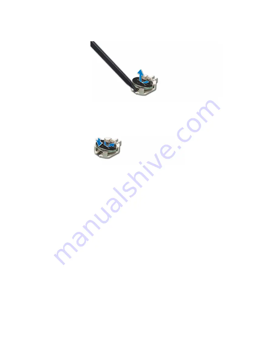
Figure 68 Removing system battery

3. To install a new system battery, hold the battery with the positive side facing up

and slide it under the securing tabs.

4. Press the battery into the connector until it snaps into place.

Figure 69 Installing system battery

Verify the battery and reset the time and date

To return the node to operation, perform the following steps:

Procedure

1. Power on the server.

2. While the system is booting, press F2 to enter System Setup.

3. Ensure that the battery is operating properly.

4. Select System BIOS

 > 

Miscellaneous Settings.

5. Enter the correct time and date in the System Time and System Date fields,

respectively.

6. Exit System Setup.

Hardware FRU procedures

Verify the battery and reset the time and date


149

Summary of Contents for EMC VxFlex Ready Node R840

Page 1: ...Dell EMC VxFlex Ready Node R840 Hardware Field Replacement Unit and Service Manual P N 302 005 750 REV 01 ...

Page 2: ...PUBLICATION AND SPECIFICALLY DISCLAIMS IMPLIED WARRANTIES OF MERCHANTABILITY OR FITNESS FOR A PARTICULAR PURPOSE USE COPYING AND DISTRIBUTION OF ANY DELL SOFTWARE DESCRIBED IN THIS PUBLICATION REQUIRES AN APPLICABLE SOFTWARE LICENSE Dell EMC and other trademarks are trademarks of Dell Inc or its subsidiaries Other trademarks may be the property of their respective owners Published in the USA Dell ...

Page 3: ...ystem setup options 26 System BIOS 27 iDRAC Settings utility 51 Device Settings 51 Dell Lifecycle Controller 52 Embedded system management 52 Boot Manager 52 View the boot manager 52 Boot Manager main menu 52 One shot UEFI Boot menu 53 System Utilities 53 PXE boot 53 Hardware FRU procedures 55 Important information before performing a FRU procedure 56 Safety instructions 56 Recommended tools 56 Un...

Page 4: ...l a GPU card 114 Replacing an M 2 SSD module 116 Remove the M 2 SSD module 117 Install the M 2 SSD module 117 Replacing network cards 119 Replacing the network daughter card 119 Replacing a 10G NIC in a PCIe slot 122 Installing an optional NIC 123 Replacing the processor and heat sink 126 Processor replacement procedural checklist 126 Remove the processor and heat sink module 127 Removing the proc...

Page 5: ...d 169 Remove the GPU air shroud 169 Install the GPU air shroud 171 System cover 173 Remove the system cover 173 Install the system cover 173 Cooling fan assembly 174 Remove the cooling fan assembly 174 Install the cooling fan assembly 175 Removing a drive blank 176 Installing a drive blank 177 Trusted Platform Module 178 Upgrading Trusted Platform Module 178 Remove the TPM 178 Install the TPM 178 ...

Page 6: ...ator codes 204 Status LED indicators 204 System health and system ID indicator codes 205 iDRAC Quick Sync 2 indicator codes 206 iDRAC Direct LED indicator codes 207 NIC indicator codes 208 Power supply unit indicator codes 208 Hard drive indicator codes 212 Using system diagnostics 213 Dell Embedded System Diagnostics 213 Getting help 215 Where to get help 216 Contacting Dell EMC 216 Receiving aut...

Page 7: ...ackplane 87 Cable routing 24 x 2 5 inch SAS SATA drive backplane supporting x12 universal SAS SATA NVMe slots with GPU and single PERC card 88 Cable routing 24 x 2 5 inch SAS SATA drive backplane supporting with single PERC card 89 Cable routing 24 x 2 5 inch SAS SATA drive backplane with dual PERC card 89 Removing cooling fan 93 Installing cooling fan 94 Removing the expansion card from the riser...

Page 8: ...ontrol panel 162 Release and extend system from cabinet 165 Slide the system into the cabinet 165 Removing optional front bezel 166 Installing the optional front bezel 167 Removing the non GPU air shroud 168 Installing the non GPU air shroud 169 Removing the GPU air shroud cover 170 Removing the GPU air shroud 171 Installing the GPU air shroud 172 Installing the GPU air shroud cover 172 Removing t...

Page 9: ...pecifications 194 Relative humidity specifications 194 Maximum vibration specifications 195 Maximum shock pulse specifications 195 Maximum altitude specifications 195 Operating temperature derating specification 195 Standard operating temperature specifications 196 Expanded operating temperature specifications 196 Configuration based ambient temperature restrictions 198 Configuration based ambient...

Page 10: ...TABLES 10 VxFlex Ready Node R840 Hardware Field Replacement Unit and Service Manual ...

Page 11: ... helps you make better use of your product CAUTION A CAUTION indicates either potential damage to hardware or loss of data and tells you how to avoid the problem WARNING A WARNING indicates a potential for property damage personal injury or death Notes cautions and warnings 11 ...

Page 12: ...Notes cautions and warnings 12 VxFlex Ready Node R840 Hardware Field Replacement Unit and Service Manual ...

Page 13: ...y Node R840 system diagnostic tools and instructions for installing and replacing tools Use this document with the VxFlex Ready Node Field Replacement Unit Software Guide for FRU replacement activities l How to use this guide 14 l Typographical conventions 14 l Initial system setup and configuration 14 About this guide 13 ...

Page 14: ...te the FRU procedure and return the VxFlex OS node to operation Typographical conventions Dell EMC uses the following type style conventions in this document Bold Used for names of interface elements such as names of windows dialog boxes buttons fields tab names key names and menu paths what the user specifically selects or clicks Italic Used for full titles of publications referenced in text Mono...

Page 15: ...vides an overview of the VxFlex Ready Node R840 server l VxFlex Ready Node R840 system overview 16 l Front view of the system 16 l Rear view of the system 22 l Inside the system 23 l Locating the Service Tag of your system 23 System overview 15 ...

Page 16: ... rear accessible drives and up to 24 NVMe drives For more information about supported drives see Technical specifications Note All instances of NVMe and SSDs are referred to as drives in this document unless specified otherwise Front view of the system Figure 1 Front view 24 x 2 5 inch drive system 1 Left control panel 2 Drives 3 Right control panel 4 Service Tag System overview 16 VxFlex Ready No...

Page 17: ...erent backplane and is only for the compute only node This option is supported by VxFlex Ready Node and the appliance but is NOT supported by VxRack FLEX Control panels Left control panel Figure 3 Left control panel view with optional iDRAC Quick Sync 2 0 indicator 1 Status LED indicators 2 System health and system ID indicator 3 iDRAC Quick Sync 2 wireless indicator optional System overview Contr...

Page 18: ...Integrated Dell Remote Access Controller User s Guide at www dell com idracmanuals Note For more information about the indicator codes see System diagnostics and indicator codes Right control panel view Figure 4 Right control panel view 1 Power button 2 USB 2 0 port 2 3 iDRAC Direct port 4 iDRAC Direct LED 5 VGA port Note For more information on the ports see Technical specifications System overvi...

Page 19: ...xt Note If the system is connected to a power source and an error is detected the LCD turns amber regardless of whether the system is turned on or off l When the system turns off and there are no errors LCD enters the standby mode after five minutes of inactivity Press any button on the LCD to turn it on l If the LCD panel stops responding remove the bezel and reinstall it If the problem persists ...

Page 20: ...teps a Press and hold the navigation button until the up arrow is displayed b Navigate to the Home icon using the up arrow c Select the Home icon d On the Home screen press the Select button to enter the main menu Setup menu Note When you select an option in the Setup menu you must confirm the option before proceeding to the next action Option Description iDRAC Select DHCP or Static IP to configur...

Page 21: ...IPv4 or IPv6 addresses for iDRAC9 Addresses include DNS Primary and Secondary Gateway IP and Subnet IPv6 does not have Subnet MAC Displays the MAC addresses for iDRAC iSCSI or Network devices Name Displays the name of the Host Model or User String for the system Number Displays the Asset tag or the Service tag for the system Power Displays the power output of the system in BTU hr or Watts The disp...

Page 22: ... slots located on the system board Slot 3 and 4 3 Riser 2 Full height PCIe expansion card slots Slot 5 and 6 4 Power supply units 2 5 System identification button 6 iDRAC9 dedicated port 7 USB 3 0 ports 2 8 VGA port 9 Serial port 10 NIC ports 4 11 Rear handle Note For more information about the ports and connectors see Technical specifications System overview 22 VxFlex Ready Node R840 Hardware Fie...

Page 23: ...rd Riser 1 7 Intrusion switch Locating the Service Tag of your system You can identify your system using the unique Express Service Code and Service Tag Pull out the information tag in the front of the system to view the Express Service Code and Service Tag Alternatively the information may be on a sticker on the chassis of the system The mini Enterprise Service Tag EST is found on the back of the...

Page 24: ...ve opted for secure default access to iDRAC the iDRAC secure default password is available on the back of the system Information tag This section of label will be blank if you have not opted for secure default access to iDRAC then the default user name and password are root and Scaleio123 respectively 5 Service Tag System overview 24 VxFlex Ready Node R840 Hardware Field Replacement Unit and Servi...

Page 25: ... system firmware CAUTION Changing the default settings may make the node unusable Dell EMC recommends only making changes under the direction of Dell EMC tech support l Options for managing preoperating system applications 26 l Using the system setup 26 l Dell Lifecycle Controller 52 l Boot Manager 52 l PXE boot 53 Managing basic system settings using the system firmware 25 ...

Page 26: ...ed by default l Text browser The browser is enabled by using Console Redirection Note Help text for the selected field is displayed in the graphical browser by default To view the help text in the text browser press F1 View system setup To view the System Setup screen perform the following steps Procedure 1 Turn on or restart the server 2 Press F2 immediately after you see the following message F2...

Page 27: ...ormation screen allows you to view system properties such as the service tag system model name and BIOS version View system information To view system information perform the following steps Procedure 1 Turn on or restart your system 2 Press F2 immediately after you see the following message F2 System Setup Note If your operating system begins to load before you press F2 wait for the system to fin...

Page 28: ...m the following steps Procedure 1 Turn on or restart the server 2 Press F2 immediately after you see the following message F2 System Setup Note If the operating system begins to load before you press F2 wait for the system to finish booting and then restart the server and try again 3 On the System Setup Main Menu screen click System BIOS 4 On the System BIOS screen click Memory Settings Memory Set...

Page 29: ...Specifies the current state of the memory operating mode Node Interleaving Specifies whether Non Uniform Memory Architecture NUMA is supported If this field is set to Enabled memory interleaving is supported if a symmetric memory configuration is installed If the field is set to Disabled the system supports NUMA asymmetric memory configurations The default is Disabled which is set in the System Id...

Page 30: ...bled by default CPU Interconnect Speed Enables you to govern the frequency of the communication links among the CPUs in the system Note The standard and basic bin processors support lower link frequencies The options available are Maximum data rate 10 4 GT s and 9 6 GT s This option is set to Maximum data rate by default Maximum data rate indicates that the BIOS runs the communication links at the...

Page 31: ... in the system It improves average latency to the LLC Enables or disables the Sub NUMA Cluster This option is set to Disabled by default UPI Prefetch Enables you to get the memory read started early on DDR bus The Ultra Path Interconnect UPI Rx path will spawn the speculative memory read to Integrated Memory Controller iMC directly This option is set to Enabled by default Logical Processor Idling ...

Page 32: ...n The following settings are displayed for each processor installed in the system Family Model Stepping Specifies the family model and stepping of the processor as defined by Intel Brand Specifies the brand name Level 2 Cache Specifies the total L2 cache Level 3 Cache Specifies the total L3 cache Number of Cores Specifies the number of cores per processor SATA settings Use the SATA Settings screen...

Page 33: ...k command to the embedded SATA drives during POST This option is set to Enabled by default Write Cache Enables or disables the command for the embedded SATA drives during POST This option is set to Disabled by default Port n Sets the drive type of the selected device For AHCI Mode or RAID Mode BIOS support is always enabled Option Description Model Specifies the drive model of the selected device ...

Page 34: ...e setting to Non RAID mode View NVMe settings To view the NVMe Settings screen perform the following steps Procedure 1 Turn on or restart your system 2 Press F2 immediately after you see the following message F2 System Setup Note If your operating system begins to load before you press F2 wait for the system to finish booting and then restart your system and try again 3 On the System Setup Main Me...

Page 35: ... runtime service calls that are available to the operating system and its loader The following benefits are available when the Boot Mode is set to UEFI n Support for drive partitions larger than 2 TB n Enhanced security e g UEFI Secure Boot n Faster boot time Note You must use only the UEFI boot mode in order to boot from NVMe drives View Boot Settings To view the Boot Settings screen perform the ...

Page 36: ... for UEFI Boot Mode This option is set to Disabled by default UEFI Boot Settings The UEFI Boot Settings screen enables you to specify the UEFI boot order UEFI Boot Sequence Enables you to change the UEFI boot device order Boot Options Enable Disable Enables you to enable or disable the UEFI boot devices Network settings Use the network settings to modify UEFI PXE iSCSI and HTTP boot settings The n...

Page 37: ...ce HTTP Device n Settings n 1 to 4 Enables you to control the configuration of the HTTP device UEFI iSCSI Settings Enables you to control the configuration of the iSCSI device Table 2 UEFI iSCSI Settings screen details Option Description iSCSI Initiator Name Specifies the name of the iSCSI initiator in IQN format iSCSI Device1 Enables or disables the iSCSI device When disabled a UEFI boot option i...

Page 38: ...sabled dynamically by authorized users without resetting the system The USB keyboard and mouse still function in certain USB ports during the boot process depending on the selection After the boot process is complete the USB ports will be enabled or disabled as per the setting Internal USB Port Enables or disables the internal USB port This option is set to On by default iDRAC Direct USB Port The ...

Page 39: ...urrent State of Embedded Video Controller option is a read only field If the Embedded Video Controller is the only display capability in the system that is no add in graphics card is installed then the Embedded Video Controller is automatically used as the primary display even if the Embedded Video Controller setting is set to Enabled SR IOV Global Enable Enables or disables the BIOS configuration...

Page 40: ...oot driver is disabled for the PCIe slot 3 This option is set to Enabled by default Slot 4 Enables or disables or only the boot driver is disabled for the PCIe slot 4 This option is set to Enabled by default Slot 5 Enables or disables or only the boot driver is disabled for the PCIe slot 5 This option is set to Enabled by default Slot 6 Enables or disables or only the boot driver is disabled for t...

Page 41: ...furcation Slot 4 Bifurcation x16 Bifurcation or x8 Bifurcation or x4 Bifurcation or x4 x4 x8 Bifurcation or x8 x4 x4 Bifurcation Slot 5 Bifurcation x4 Bifurcation or x8 Bifurcation Slot 6 Bifurcation x x16 Bifurcation or x8 Bifurcation or x4 Bifurcation or x4 x4 x8 Bifurcation or x8 x4 x4 Bifurcation Serial Communication Use the Serial Communication screen to view the properties of the serial comm...

Page 42: ... set to Serial Device 2 COM1 by default Note You can use only Serial Device 2 for the Serial Over LAN SOL feature To use console redirection by SOL configure the same port address for console redirection and the serial device External Serial Connector Enables you to associate the External Serial Connector to Serial Device 1 Serial Device 2 or the Remote Access Device by using this option This opti...

Page 43: ...rform the following steps Procedure 1 Turn on or restart your system 2 Press F2 immediately after you see the following message F2 System Setup Note If your operating system begins to load before you press F2 wait for the system to finish booting and then restart your system and try again 3 On the System Setup Main Menu screen click System BIOS 4 On the System BIOS screen click System Profile Sett...

Page 44: ...b Sets the memory patrol scrub frequency This option is set to Standard by default Memory Refresh Rate Sets the memory refresh rate to either 1x or 2x This option is set to 1x by default Uncore Frequency Enables you to select the Processor Uncore Frequency option Dynamic mode enables the processor to optimize power resources across the cores and uncore during runtime The optimization of the uncore...

Page 45: ...gement Enables or disables the PCI ASPM L1 Link Power Management This option is set to Enabled by default System security Use the System Security screen to perform specific security functions such as setting the system password and disabling the power button View System Security options To view the System Security screen perform the following steps Procedure 1 Turn on or restart the server 2 Press...

Page 46: ...rements or On without Pre boot Measurements When TPM 1 2 is installed the TPM Security option is set to Off On with Pre boot Measurements or On without Pre boot Measurements This tables describes TPM 1 2 security information Table 5 TPM 1 2 security information TPM information Description TPM Information Changes the operational state of the TPM This option is set to No Change by default TPM Firmwa...

Page 47: ...em This option is set to Enabled by default AC Power Recovery Sets how the system behaves after AC power is restored to the system This option is set to Last by default AC Power Recovery Delay Sets the time delay for the system to power up after AC power is restored to the system This option is set to Immediate by default User Defined Delay 60 s to 240 s Sets the User Defined Delay option when the...

Page 48: ...r Mode Audit Mode and Deployed Mode Options Description User Mode In User Mode PK must be installed and BIOS performs signature verification on programmatic attempts to update policy objects The BIOS allows unauthenticated programmatic transitions between modes Deployed Mode Deployed Mode is the most secure mode In Deployed Mode PK must be installed and the BIOS performs signature verification on ...

Page 49: ... press F2 wait for the system to finish booting and then restart the server and try again 3 On the System Setup Main Menu screen click System BIOS 4 On the System BIOS screen click Redundant OS Control Redundant OS Control screen details The Redundant OS Control screen details are explained as follows Redundant OS Location Enables you to select a backup disk from the following devices l None l Int...

Page 50: ...m date and time CAUTION Changing the default settings may make the node unusable Dell EMC recommends only making changes under the direction of Dell EMC tech support View Miscellaneous Settings To view the Miscellaneous Settings screen perform the following steps Procedure 1 Turn on or restart your system 2 Press F2 immediately after you see the following message F2 System Setup Note If your opera...

Page 51: ...ode is enabled This option is set to Disabled by default Dell Wyse P25 P45 BIOS Access Enables or disables the Dell Wyse P25 P45 BIOS Access This option is set to Enabled by default Power Cycle Request Enables or disables the Power Cycle Request This option is set to None by default iDRAC Settings utility The iDRAC settings utility is an interface for setting up and configuring the iDRAC parameter...

Page 52: ...ee the Dell Lifecycle Controller documentation at Dell com idracmanuals CAUTION Changing the default settings may make the node unusable Dell EMC recommends only making changes under the direction of Dell EMC tech support Boot Manager The Boot Manager screen enables you to select boot options and diagnostic utilities CAUTION Changing the default settings may make the node unusable Dell EMC recomme...

Page 53: ...e shot UEFI Boot menu The One shot UEFI Boot menu enables you to access the UEFI Boot menu and select a one shot boot option from which to boot CAUTION Changing the default settings may make the node unusable Dell EMC recommends only making changes under the direction of Dell EMC tech support System Utilities System Utilities contains the following utilities that can be launched l Launch Diagnosti...

Page 54: ...Managing basic system settings using the system firmware 54 VxFlex Ready Node R840 Hardware Field Replacement Unit and Service Manual ...

Page 55: ...ng the BOSS card 58 l Replacing drives 66 l Replacing system memory modules 74 l Replacing the hard drive backplane 81 l Replacing cooling fans 91 l Replacing an expansion card or expansion card riser 95 l Replacing the GPU card 112 l Replacing an M 2 SSD module 116 l Replacing network cards 119 l Replacing the processor and heat sink 126 l Replacing the storage controller card 136 l Replacing the...

Page 56: ...bleshooting and simple repairs as authorized in your product documentation or as directed by the online or telephone service and support team Damage due to servicing that is not authorized by Dell EMC is not covered by your warranty Read and follow the safety instructions that came with the product WARNING Always use a static mat and anti static wristband while working on components inside the sys...

Page 57: ...n from size 10 AWG solid or stranded insulated copper wire Note Use alpha wire part number 3080 or equivalent 65 30 stranding Unpack the part Procedure 1 Wear ESD gloves or attach an ESD wristband to your wrist and the enclosure in which you are installing the part 2 Unpack the part and place it on a static free surface 3 If the part is a replacement for a faulted part save the packing material to...

Page 58: ...ry software tasks to prepare the node for part replacement 2 Gracefully shut down the node See Gracefully shut down the node in the VxFlex Ready Node Field Replacement Unit Software Guide Return to this guide for instructions on replacing the system component 3 Prepare the replacement BOSS card See Prepare the replacement BOSS card on page 59 4 Remove the bezel See Remove the front bezel on page 1...

Page 59: ... Verify the new BOSS card in the server according to the server s operating system type 16 Return the node to operation Prepare the replacement BOSS card The replacement BOSS card includes two M 2 modules You must remove these two modules so you can later migrate the M 2 modules on the faulted BOSS card to the replacement BOSS card Before you begin Follow all safety guidelines Procedure 1 Unpack t...

Page 60: ...ou begin Follow all safety guidelines Procedure 1 Pull the expansion card latch out of the slot 2 Hold the BOSS card by its edges and pull the card until the card edge connector disengages from the expansion card connector on the riser Hardware FRU procedures 60 VxFlex Ready Node R840 Hardware Field Replacement Unit and Service Manual ...

Page 61: ...fer the two M 2 modules from the faulted BOSS card to the replacement BOSS card Before you begin Follow all safety guidelines Procedure 1 On the faulted BOSS card unfasten the screw that secures the M 2 module on the BOSS card 2 Lift the M 2 module away from the BOSS card Hardware FRU procedures Transfer the M 2 modules to the replacement BOSS Card 61 ...

Page 62: ...lign the M 2 module connectors with the connectors on the BOSS card 4 Tilt the M 2 module downwards until the module is seated firmly on the card 5 Tighten the screw that secures the M 2 module on the BOSS card Hardware FRU procedures 62 VxFlex Ready Node R840 Hardware Field Replacement Unit and Service Manual ...

Page 63: ...ll the expansion card latch out of the slot 2 Hold the BOSS card by its edges and align the card edge connector with the expansion card connector on the riser 3 Insert the BOSS card edge connector firmly into the expansion card connector until the card is fully seated 4 Push the expansion card latch into the slot Hardware FRU procedures Install the BOSS card onto expansion card riser 1 63 ...

Page 64: ...faulted BOSS card Before you begin Follow all safety guidelines Procedure 1 Align the M 2 module connectors with the connectors on the BOSS card 2 Tilt the M 2 module downwards until the module is seated firmly on the card 3 Tighten the screw that secures the M 2 module on the BOSS card Hardware FRU procedures 64 VxFlex Ready Node R840 Hardware Field Replacement Unit and Service Manual ...

Page 65: ...Figure 14 Installing the M 2 module 1 module connector 2 2 screws 2 3 modules 2 Hardware FRU procedures Install M 2 modules on the faulted BOSS card 65 ...

Page 66: ...ist in the order they are listed Note Before starting this FRU procedure familiarize yourself with the topics in Important information before performing a FRU procedure on page 56 CAUTION This FRU procedure requires you to perform mandatory software tasks in VxFlex OS as described in the VxFlex Ready Node Field Replacement Unit Software Guide You will be referred to these mandatory software tasks ...

Page 67: ...ezel See Install the front bezel on page 166 Perform mandatory software tasks to return the node to operation 9 Return the node to operation See Replacing an SSD drive in the VxFlex Ready Node Field Replacement Unit Software Guide Perform all required software related tasks listed after replacing the drive based on the VxFlex OS configuration and the node s operating system type CAUTION Failure to...

Page 68: ...o perform all required software related tasks before replacing a drive may result in loss of data Return to this guide for instructions on replacing the system component 4 Remove the front bezel See Remove the front bezel on page 166 5 Remove the hard drive carrier See Remove the drive carrier on page 69 6 Remove the NVMe drive See Remove the drive from the drive carrier on page 70 7 Install the r...

Page 69: ... Guide If the drive is online the green activity or fault indicator flashes while the drive is turning off When the drive indicators are off the drive is ready for removal For more information see the storage controller documentation CAUTION Mixing drive carriers from previous generations of VxFlex Ready Node servers is not supported Procedure 1 Press the release button to open the drive carrier r...

Page 70: ...ng drive carriers from previous generations of VxFlex Ready Node servers is not supported Procedure 1 Using a Phillips 1 screwdriver remove the screws from the slide rails on the drive carrier 2 Lift the drive out of the drive carrier Hardware FRU procedures 70 VxFlex Ready Node R840 Hardware Field Replacement Unit and Service Manual ...

Page 71: ... drive carrier with the connector end of the drive towards the back of the carrier 2 Align the screw holes on the drive with the screws holes on the drive carrier When aligned correctly the back of the drive is flush with the back of the drive carrier 3 Using a Phillips 1 screwdriver secure the drive to the drive carrier with screws Note When installing a drive into the drive carrier ensure that t...

Page 72: ...stalled carrier can damage the partially installed carrier s shield spring and make it unusable Note When a replacement hot swappable drive is installed and the system is powered on the drive automatically begins to rebuild Ensure that the replacement drive is blank or contains data that you wish to overwrite Any data on the replacement drive is immediately lost after the drive is installed Proced...

Page 73: ...3 Close the drive carrier release handle to lock the drive in place Figure 18 Installing a drive carrier Hardware FRU procedures Install the drive carrier 73 ...

Page 74: ...age 74 l Replacing a DIMM memory module on page 77 Overview of system memory The system contains 48 memory sockets split into four sets of 12 sockets one set per processor Each 12 socket set is organized into six channels Six memory channels are allocated to each processor In each channel the release tabs of the first socket are marked white and the second socket black Hardware FRU procedures 74 V...

Page 75: ...hannel 3 Channel 4 Channel 5 Processor 1 Slots A1 and A7 Slots A2 and A8 Slots A3 and A9 Slots A4 and A10 Slots A5 and A11 Slots A6 and A12 Processor 2 Slots B1 and B7 Slots B2 and B8 Slots B3 and B9 Slots B4 and B10 Slots B5 and B11 Slots B6 and B12 Processor 3 Slots C1 and C7 Slots C2 and C8 Slots C3 and C9 Slots C4 and C10 Slots C5 and C11 Slots C6 and C12 Hardware FRU procedures Overview of sy...

Page 76: ... following are the recommended guidelines for installing memory modules l All DIMMs must be DDR4 l RDIMMs and LRDIMMs must not be mixed l NVDIMMs and LRDIMMs must not be mixed l NVDIMMs and RDIMMs can be mixed l 64 GB LRDIMMs that are DDP Dual Die Package LRDIMMs must not be mixed with 128 GB LRDIMMs that are TSV Through Silicon Via 3DS LRDIMMs l x4 and x8 DRAM based memory modules can be mixed l ...

Page 77: ...maximize performance l To ensure proper system cooling memory module blanks must be installed in memory sockets that are not occupied DIMM population update for Performance Optimized mode with quantity of 4 and 8 DIMMs per processor l When the DIMM quantity is 4 per processor the population is slot 1 2 4 5 l When the DIMM quantity is 8 per processor the population is slot 1 2 4 5 7 8 10 11 Replaci...

Page 78: ...e GPU air shroud on page 169 9 Remove the faulty system memory module See Remove a memory module on page 78 10 Install the replacement system memory module See Install a memory module on page 79 11 Install the air shroud See Install the non GPU air shroud on page 169 or Install the GPU air shroud on page 171 12 Replace the system cover See Install the system cover on page 173 13 Slide the system i...

Page 79: ...e socket CAUTION Handle each memory module only by the card edges ensuring not to touch the middle of the memory module or metallic contacts 2 Push the ejectors outward on both ends of the memory module socket to release the memory module from the socket 3 Lift and remove the memory module from the system Figure 20 Removing a memory module Note If you are removing the memory module permanently ins...

Page 80: ... socket 3 Align the edge connector of the memory module with the alignment key of the memory module socket and insert the memory module in the socket CAUTION Do not apply pressure at the center of the memory module apply pressure at both ends of the memory module evenly Note The memory module socket has an alignment key that enables you to install the memory module in the socket in only one orient...

Page 81: ...erver for part replacement See Gracefully shut down the node in the VxFlex Ready Node Field Replacement Unit Software Guide Return to this guide for instructions on replacing the system component 3 Remove the bezel See Remove the front bezel on page 166 4 Disconnect the power cords and I O cables See Disconnect the power cords and I O cables on page 164 5 Extend the system from the cabinet See Ext...

Page 82: ...cover See Install the system cover on page 173 16 Slide the system into the cabinet See Slide the system into the cabinet on page 165 17 Connect the cable cords See Connect the I O cables and power cords on page 164 18 Install the front bezel See Install the front bezel on page 166 Perform mandatory software tasks to return the node to operation 19 Return the node to operation See Return the node ...

Page 83: ...Ie cable connector 4 PCIe cable connector 5 Backplane signal connector 6 SAS SATA cable connector 7 Power cable connector 8 Backplane signal connector 9 Power cable connector Figure 24 2 5 inch x24 SAS SATA expander with universal slot for NVMe backplane 1 SAS cable connector A 2 SAS cable connector B 3 Backplane signal connector J_BP_SIG 4 Power cable connector J_PWR_A Hardware FRU procedures Dri...

Page 84: ...drive chassis Figure 25 Twenty four drive SAS SATA Up to twenty four 2 5 inch SAS SATA front accessible drives in slots 0 through 23 Figure 26 Twelve twelve NVMe Up to twelve 2 5 inch SAS SATA front accessible drives in slots 0 through 11 twelve SAS SATA NVMe front accessible drives in slots 12 through 23 Figure 27 Twenty four drive NVMe Up to twenty four 2 5 inch NVMe front accessible drives in s...

Page 85: ...moved Remove the drive backplane Before you begin Follow all safety guidelines CAUTION To prevent damage to the drives and backplane remove the drives from the system before removing the backplane CAUTION Note the number of each drive and temporarily label them before you remove the drive so that you can replace them in the same location Note The procedure to remove the backplane is similar for al...

Page 86: ...egin Follow all safety guidelines Procedure 1 Connect the cables a If applicable connect the slimline SAS I2C and power cables to the backplane b Connect the I2C and power cables to the system board 2 Holding the blue release tabs align the slots on the backplane with the hooks on the system 3 Lower the drive backplane until the blue release tabs snap into place Hardware FRU procedures 86 VxFlex R...

Page 87: ...Figure 30 Installing drive backplane 4 If applicable connect the slimline SAS cable to the system board Hardware FRU procedures Install the drive backplane 87 ...

Page 88: ...h SAS SATA drive backplane supporting x12 universal SAS SATA NVMe slots with GPU and single PERC card Note VxFlex Ready Node R840 does not support PERC Hardware FRU procedures 88 VxFlex Ready Node R840 Hardware Field Replacement Unit and Service Manual ...

Page 89: ...porting with single PERC card Note VxFlex Ready Node R840 does not support PERC Figure 33 Cable routing 24 x 2 5 inch SAS SATA drive backplane with dual PERC card Note VxFlex Ready Node R840 does not support PERC Hardware FRU procedures Install the drive backplane 89 ...

Page 90: ... location it was removed from Procedure 1 Refer to Install the drive into the drive carrier on page 71 and install the hard drives in the same location from which each one was removed Hardware FRU procedures 90 VxFlex Ready Node R840 Hardware Field Replacement Unit and Service Manual ...

Page 91: ...lowing checklist in the order they are listed The tasks are used for all OS types Cooling fans are hot swappable and do not require any software steps in VxFlex OS to prepare the server for the part replacement or return it operation after replacing the fan Note Before starting this FRU procedure familiarize yourself with the topics in Important information before performing a FRU procedure on pag...

Page 92: ...the cabinet on page 165 Remove a cooling fan The cooling fans are hot swappable To maintain proper cooling while the server is on replace only one fan at a time Before you begin Follow all safety guidelines CAUTION Opening or removing the system cover when the server is on may expose you to a risk of electric shock Exercise utmost care while removing or installing cooling fans Procedure 1 Press th...

Page 93: ...or removing the system cover when the server is on may expose you to a risk of electric shock Exercise utmost care while removing or installing cooling fans Procedure 1 Holding the touch points on the cooling fan align the connector on the cooling fan with the connector on the system board 2 Slide the cooling fan into the cooling fan assembly until the release tab locks into place Hardware FRU pro...

Page 94: ...Figure 35 Installing cooling fan Hardware FRU procedures 94 VxFlex Ready Node R840 Hardware Field Replacement Unit and Service Manual ...

Page 95: ...r Check List Task Topic 1 Identify the faulty part See System diagnostics and indicator codes on page 203 Perform mandatory software tasks to prepare the node for part replacement 2 Prepare the server for part replacement See Gracefully shut down the node in the VxFlex Ready Node Field Replacement Unit Software Guide Return to this guide for instructions on replacing the system component 3 Remove ...

Page 96: ...he system into the cabinet See Slide the system into the cabinet on page 165 15 Connect the I O cables and power cords See Connect the I O cables and power cords on page 164 16 Install the bezel See Install the front bezel on page 166 Perform mandatory software tasks to return the node to operation 17 Return the node to operation See Return the node to operation in the VxFlex Ready Node Field Repl...

Page 97: ...fault expansion card locations The tables referenced below are for information purposes only Note The expansion card slots are not hot swappable This table shows the x16 PCIe riser 1 x16 PCIe riser 2 configuration details Table 10 x16 PCIe riser 1 x16 PCIe riser 2 configuration Card type Card priority Slot priority Riser height Maximum number of cards supported Card height Card length Maximum PCIe...

Page 98: ...e x4 2800 3 4 Low profile 1 Half length Low profile x4 2900 3 4 Low profile 1 Half length Low profile x8 External RAID 3000 3 4 Low profile 2 Half length Low profile x8 3100 3 4 Low profile 2 Half length Low profile x8 3200 2 6 Full height 2 Half length Full height x8 3300 2 6 Full height 2 Half length Full height x8 Infiniband HCA FDR 3400 3 4 Low profile 2 Half length Low profile x8 40Gb NICs 35...

Page 99: ...200 3 4 Low profile 2 Half length Low profile x4 7300 3 4 Low profile 2 Half length Low profile x8 7400 3 4 Low profile 2 Half length Low profile x8 7500 2 6 Full height 2 Half length Full height x8 7600 2 6 Full height 2 Half length Low profile x8 7700 2 6 Full height 2 Half length Low profile x8 7800 3 4 Low profile 2 Half length Low profile x8 7900 3 4 Low profile 2 Half length Low profile x8 8...

Page 100: ...10900 2 6 Full height 2 Half length Full height x8 NVMe PCIe SSD 11000 3 4 2 6 Full height or Low profile 2 Half length Full height or Low profile x8 11100 3 4 2 6 Full height or Low profile 2 Half length Full height or Low profile x8 11200 3 4 2 6 Full height or Low profile 2 Half length Full height or Low profile x8 11300 3 4 2 6 Full height or Low profile 2 Half length Full height or Low profil...

Page 101: ...ed Slot None 1 None rNDC x8 13100 Integrated Slot None 1 None rNDC x8 Remove the expansion card from the expansion card riser The procedure to remove the expansion card from the riser is identical for all risers This procedure should also be used when removing a NIC from a PCIe slot Before you begin Follow all safety guidelines Note The parent hardware offers a variety of risers so the images belo...

Page 102: ...nstall a filler bracket over an empty expansion card slot to maintain Federal Communications Commission FCC certification of the system The brackets also keep dust and dirt out of the system and aid in proper cooling and airflow inside the system Hardware FRU procedures 102 VxFlex Ready Node R840 Hardware Field Replacement Unit and Service Manual ...

Page 103: ...isconnect any cables connected to the riser Procedure 1 Using the Phillips 2 screwdriver loosen the screws that secure the riser to the system 2 Press the blue release tab and holding the riser by its edges lift the riser from the riser connector on the system board Hardware FRU procedures Expansion cards and expansion card risers 103 ...

Page 104: ...e 38 Removing the expansion card x16 PCIe riser 1 Figure 39 Removing the expansion card x16 PCIe riser 2 Hardware FRU procedures 104 VxFlex Ready Node R840 Hardware Field Replacement Unit and Service Manual ...

Page 105: ...he riser 2 Open the blue card holder latch on the riser 3 If installed remove the filler bracket Figure 40 Removing a filler bracket from a riser Note If applicable connect the cables to the expansion card 4 Hold the card by its edges and align the card edge connector with the connector on the riser 5 Insert the card edge connector firmly into the expansion card connector until the card is fully s...

Page 106: ...n card risers 2 Holding the touch points align the slots on the riser with the guides on the system board and air shroud 3 Lower the expansion card riser into place until the expansion card riser connector is fully seated in the connector 4 Tighten the captive screws to secure the riser to the system Hardware FRU procedures 106 VxFlex Ready Node R840 Hardware Field Replacement Unit and Service Man...

Page 107: ...e riser 1 Figure 43 Installing the expansion card x16 PCIe riser 2 After you finish Install any device drivers required for the card as described in the documentation for the card Hardware FRU procedures Expansion cards and expansion card risers 107 ...

Page 108: ... the system board connector Figure 44 Removing an expansion card from the system board 3 If you are not replacing the expansion card install a filler bracket by performing the following steps a Align the slot on the filler bracket with the tab on the expansion card slot b Align the filler bracket with the slot on the system c Push the filler bracket downward until firmly seated d Close the blue ex...

Page 109: ... performing a FRU procedure on page 56 Procedure 1 Unpack the expansion card and prepare it for installation For instructions see the documentation accompanying the card 2 If you are installing a new card remove the filler bracket a Open the blue expansion card retention latch lock b Slide the filler bracket out of the system Hardware FRU procedures Expansion cards and expansion card risers 109 ...

Page 110: ...the system and aid in proper cooling and airflow inside the system 3 Holding the card on the edges align the card with the expansion card connector on the system board 4 Press the expansion card firmly into the expansion card connector on the system board until the card is fully seated 5 Close the blue expansion card retention latch Hardware FRU procedures 110 VxFlex Ready Node R840 Hardware Field...

Page 111: ...Figure 47 Installing an expansion card on the system board Hardware FRU procedures Expansion cards and expansion card risers 111 ...

Page 112: ...de for GPU replacement See GPU card replacement procedural checklist in the VxFlex Ready Node Field Replacement Unit Software Guide Perform all software related tasks listed up until you are directed back to this guide to replace the actual component Return to this guide for instructions on replacing the system component 3 Disconnect the power cords and I O cables See Disconnect the power cords an...

Page 113: ...at the system meets the following guidelines l Ensure that both the processors are installed l The processor must use the GPU kit low profile heat sink l To ensure adequate cooling when one or more GPUs are installed the ambient inlet temperature is restricted to 30 C for CPU 150 W 8 C 165 W 12 C 200 W 205 W For more information see Ambient temperature limitations on page 198 l All GPUs must be of...

Page 114: ...ll a GPU card Before you begin Follow all safety guidelines Procedure 1 Connect the GPU power cable to the connector on the GPU 2 Open the expansion card latch and the card holder latch on the riser 3 If applicable remove the existing expansion card or filler bracket from the riser Note Install a filler bracket over any empty expansion card slots to maintain Federal Communications Commission FCC c...

Page 115: ...ctor 6 Insert the card firmly into the expansion card connector until the card is fully seated 7 Close the expansion card latch and the card holder latch Figure 49 Installing the GPU card on the riser 8 Connect the other end of the GPU power cable to the PIB Hardware FRU procedures Install a GPU card 115 ...

Page 116: ...n the node in the VxFlex Ready Node Field Replacement Unit Software Guide Return to this guide for instructions on replacing the system component 3 Remove the bezel See Remove the front bezel on page 166 4 Disconnect the power cords and I O cables See Disconnect the power cords and I O cables on page 164 5 Extend the system from the cabinet See Extend the system from the cabinet on page 164 6 Remo...

Page 117: ...ield Replacement Unit Software Guide Perform the relevant tasks starting with Rebuild the M 2 cards as a RAID device 16 Return the node to operation Remove the M 2 SSD module Before you begin Follow all safety guidelines Procedure 1 Loosen the screw and lift the retention strap that secures the M 2 SSD module on the BOSS card 2 Lift the M 2 SSD module and slide it out of the connector on the BOSS ...

Page 118: ...ard 2 Push the module down until firmly seated on the card 3 Secure the module to the card with the retention strap and then using the Phillips 1 screwdriver tighten the screw Figure 51 Installing the M 2 SSD module Hardware FRU procedures 118 VxFlex Ready Node R840 Hardware Field Replacement Unit and Service Manual ...

Page 119: ... mandatory software tasks to prepare the node for part replacement 1 Gather the server information required for performing the NDC replacement See Network card replacement procedural checklist in the VxFlex Ready Node Field Replacement Unit Software Guide Perform the relevant tasks starting with Gathering server information until you are directed back to this guide for the actual hardware replacem...

Page 120: ... setup See Network card replacement procedural checklist in the VxFlex Ready Node Field Replacement Unit Software Guide Perform the relevant tasks starting with until you are directed back to this guide for Verify the NIC in System Setup BIOS 17 Verify the new network card in the server 18 Return the node to operation Remove the network daughter card Procedure 1 Using a Phillips 2 screwdriver loos...

Page 121: ...t through the slot in the chassis 2 Align the captive screws on the card with the screw holes on the system board 3 Press the touch points on the card until the card connector is firmly seated on the system board connector 4 Using a Phillips 2 screwdriver tighten the captive screws to secure the NDC to the system board Hardware FRU procedures Replacing the network daughter card 121 ...

Page 122: ...wing checklist Che ck List Task Topic Perform mandatory software tasks to prepare the node for part replacement 1 Gather the server information required for performing the NDC replacement See Network card replacement procedural checklist in the VxFlex Ready Node Field Replacement Unit Software Guide Perform the relevant tasks starting with Gathering server information until you are directed back t...

Page 123: ...e tasks to return the node to operation 14 Verify the NIC in system setup See Network card replacement procedural checklist in the VxFlex Ready Node Field Replacement Unit Software Guide Perform the relevant tasks starting with until you are directed back to this guide for Verify the NIC in System Setup BIOS 15 Verify the new network card in the server 16 Return the node to operation Installing an...

Page 124: ...move the system cover See Remove the system cover on page 173 8 Install the optional NIC into expansion card riser 1 See Install the network interface card into expansion card riser 1 on page 125 9 Install the system cover See Install the system cover on page 173 10 Slide the system into the cabinet See Slide the system into the cabinet on page 165 11 Connect the I O cables and power cords See Con...

Page 125: ...use Filler brackets must be installed in empty expansion card slots to maintain Federal Communications Commission FCC certification of the system The brackets also keep dust and dirt out of the system and aids in proper cooling and airflow inside the system 5 Hold the network interface card by its edges and align the card edge connector with the expansion card connector on the riser 6 Insert the c...

Page 126: ...ge 96 Quad processor configuration For quad processor configurations all installed risers will be functional Processor replacement procedural checklist To replace the processor perform the tasks in the following checklist in the order they are listed Note Before starting this FRU procedure familiarize yourself with the topics in Important information before performing a FRU procedure on page 56 CA...

Page 127: ...ule See Install the processor and heat sink module on page 134 11 Install the system cover See Install the system cover on page 173 12 Slide the system into the cabinet See Slide the system into the cabinet on page 165 13 Connect the cable cords See Connect the I O cables and power cords on page 164 14 Install the front bezel See Install the front bezel on page 166 Perform mandatory software tasks...

Page 128: ...tely c Return to the first screw and loosen it completely 2 Pushing both blue retention clips simultaneously lift the processor and heat sink module PHM 3 Set the PHM aside with the processor side facing up Figure 54 Removing the processor and heat sink module 1U Hardware FRU procedures 128 VxFlex Ready Node R840 Hardware Field Replacement Unit and Service Manual ...

Page 129: ...r and heat sink module if you are replacing the processor or heat sink This procedure is not required when replacing a system board Procedure 1 Place the heat sink with the processor side facing up 2 Insert a flat blade screwdriver into the release slot marked with a yellow label Twist do not pry the screwdriver to break the thermal paste seal 3 Push the retaining clips on the processor bracket to...

Page 130: ... to release the bracket from the processor Note Ensure that the processor and the bracket are placed in the tray after you remove the heat sink Figure 57 Removing the processor bracket Installing the processor into a processor and heat sink module Procedure 1 Place the processor in the processor tray Hardware FRU procedures 130 VxFlex Ready Node R840 Hardware Field Replacement Unit and Service Man...

Page 131: ... before you install the heat sink Figure 58 Installing the processor bracket 3 If you are using an existing heat sink remove the thermal grease from the heat sink by using a clean lint free cloth 4 Use the thermal grease syringe included with your processor kit to apply the grease in a quadrilateral design on the top of the processor CAUTION Applying too much thermal grease can result in excess gr...

Page 132: ... Ensure that the two guide pin holes on the bracket match the guide holes on the heat sink l Do not press on the heat sink fins l Ensure that the pin 1 indicator on the heat sink is aligned with the pin 1 indicator on the bracket before placing the heat sink onto the processor and bracket Hardware FRU procedures 132 VxFlex Ready Node R840 Hardware Field Replacement Unit and Service Manual ...

Page 133: ...igure 60 Installing the heat sink onto the processor 1U Figure 61 Installing the heat sink onto the processor 2U Hardware FRU procedures Installing the processor into a processor and heat sink module 133 ...

Page 134: ...ward to allow the heat sink to drop in place 3 Using the Torx T30 screwdriver tighten the screws on the heat sink in the order below a Partially tighten the first screw approximately 3 turns b Tighten the second screw completely c Return to the first screw and tighten it completely If the PHM slips off the blue retention clips when the screws are partially tightened follow these steps to secure th...

Page 135: ...Figure 62 Installing a processor and 1U heat sink module Figure 63 Installing a processor and 2U heat sink module Hardware FRU procedures Install the processor and heat sink module 135 ...

Page 136: ... software related tasks listed up until you are directed back to this guide to replace the actual component CAUTION Failure to perform all required software related tasks before replacing the storage controller card may result in loss of data 2 Gracefully shut down the node Return to this guide for instructions on replacing the system component 3 Remove the bezel See Remove the front bezel on page...

Page 137: ...o operation after replacing the storage controller card in the VxFlex Ready Node Field Replacement Unit Software Guide Remove the HBA330 controller Before you begin Follow all safety guidelines Procedure 1 Locate the PCIe slot in which the controller is located 2 Remove the screws on the bracket if any or use the system s retention clips to remove the controller from the system Note To avoid damag...

Page 138: ...stall the HBA330 controller Before you begin Follow all safety guidelines Procedure 1 Select the appropriate PCIe slot 2 Align the connector on the controller with the PCIe slot on the system Note To avoid damage to the controller hold the controller by its edges only Hardware FRU procedures 138 VxFlex Ready Node R840 Hardware Field Replacement Unit and Service Manual ...

Page 139: ...tors are firmly engaged 4 Tighten the screws on the bracket if any or use the system s retention clips to secure the controller on the system 5 Reconnect the SAS cables to the system board Hardware FRU procedures Install the HBA330 controller 139 ...

Page 140: ...oard Any attempt to remove an installed TPM plug in module breaks the cryptographic binding and the module cannot be reinstalled or installed on another system board CAUTION This FRU procedure requires you to perform mandatory software tasks in VxFlex OS as described in the VxFlex Ready Node Field Replacement Unit Software Guide You will be referred to these mandatory software tasks in the followi...

Page 141: ...54 12 Remove the expansion card risers See Remove the expansion card risers on page 103 13 Unplug the backplane cables connected to the system board See System board connectors on page 182 14 Remove the processor blanks if installed N A 15 Remove the network daughter card See Remove the network daughter card on page 120 16 Remove the system board See Remove the system board on page 142 Note When r...

Page 142: ...the front bezel on page 166 13 Restore the service tag using easy restore See Restore the Service Tag by using the Easy Restore feature on page 144 If the Service Tag is not backed up in the backup flash device enter the Service Tag manually See 14 Install the Trusted Platform Module See Install the Trusted Platform Module on page 145 15 If necessary import your new or existing iDRAC Enterprise li...

Page 143: ... front of the system 3 Incline the system board at an angle and lift the system board out of the system Figure 65 Removing system board Install the system board Before you begin Follow all safety guidelines Procedure 1 Unpack the replacement system board assembly CAUTION Do not lift the system board by holding a memory module processor or other component CAUTION Take care not to damage the system ...

Page 144: ...device If BIOS detects a new system board and the Service Tag in the backup flash device BIOS prompts the user to restore the backup information Procedure 1 Turn on the system If BIOS detects a new system board and if the Service Tag is present in the backup flash device BIOS displays the Service Tag the status of the license and the UEFI Diagnostics version 2 Perform one of the following steps Af...

Page 145: ...alling a new system board Before you begin l Follow all safety guidelines l Ensure that your operating system supports the version of the TPM being installed l Ensure that you download and install the latest BIOS firmware on your system l Ensure that the BIOS is configured to enable UEFI boot mode CAUTION After the TPM plug in module is installed it is cryptographically bound to that specific syst...

Page 146: ...Figure 67 Installing the TPM Hardware FRU procedures 146 VxFlex Ready Node R840 Hardware Field Replacement Unit and Service Manual ...

Page 147: ...klist Check List Task Topic Perform mandatory software tasks to prepare the node for part replacement 1 Gracefully shut down the node See Gracefully shut down the node in the VxFlex Ready Node Field Replacement Unit Software Guide Return to this guide for instructions on replacing the system component 2 Remove the bezel See Remove the front bezel on page 166 3 Disconnect the power cords and I O ca...

Page 148: ... time and date on page 149 Perform mandatory software tasks to return the node to operation 18 Return the node to operation See Return the node to operation after exiting System Setup in the VxFlex Ready Node Field Replacement Unit Software Guide Replace the system battery Before you begin WARNING There is a danger of a new battery exploding if it is incorrectly installed Replace the battery only ...

Page 149: ...e battery and reset the time and date To return the node to operation perform the following steps Procedure 1 Power on the server 2 While the system is booting press F2 to enter System Setup 3 Ensure that the battery is operating properly 4 Select System BIOS Miscellaneous Settings 5 Enter the correct time and date in the System Time and System Date fields respectively 6 Exit System Setup Hardware...

Page 150: ...pable and do not require a graceful shutdown Note Before starting this FRU procedure familiarize yourself with the topics in Important information before performing a FRU procedure on page 56 Check List Task Topic 1 Identify the PSU to be replaced See Power supply unit indicator codes on page 208 2 Remove the power supply unit See Remove a power supply unit on page 150 3 Install the power supply u...

Page 151: ...oweredgemanuals 3 Press the release latch and holding the PSU handle slide the PSU out of the system Figure 70 Removing the power supply unit Install a power supply unit The procedure for installing AC and DC PSUs is identical Before you begin 1 Follow all safety guidelines 2 For systems that support redundant PSU ensure that both the PSUs are of the same type and have the same maximum output powe...

Page 152: ... CAUTION When connecting the power cable to the PSU secure the cable to the PSU with the strap After you finish Note When installing hot swapping or hot adding a new PSU wait 15 seconds for the system to recognize the PSU and determine its status The PSU redundancy may not occur until discovery is complete Wait until the new PSU is discovered and enabled before you remove the other PSU The PSU sta...

Page 153: ...eplacement 2 Prepare the server for part replacement See Gracefully shut down the node in the VxFlex Ready Node Field Replacement Unit Software Guide Return to this guide for instructions on replacing the system component 3 Remove the bezel See Remove the front bezel on page 166 4 Disconnect the power cords and I O cables See Disconnect the power cords and I O cables on page 164 5 Extend the syste...

Page 154: ...mandatory software tasks to return the node to operation 19 Return the node to operation See Return the node to operation in the VxFlex Ready Node Field Replacement Unit Software Guide Removing Power Interposer Board The Power Interposer Board PIB connects the hot swappable power supply units PSUs to the system board Before you begin Follow all safety guidelines CAUTION When replacing the system b...

Page 155: ...rposer board Install the power interposer board Before you begin Follow all safety guidelines CAUTION To prevent damage to the power interposer board you must remove the power supply module s or power supply blank from the system before removing the power interposer board or power distribution board Note Ensure that the cables inside the system are correctly routed and secured using the cable secu...

Page 156: ...3 Route the cables and connect them to the system board Figure 73 Installing power interposer board Hardware FRU procedures 156 VxFlex Ready Node R840 Hardware Field Replacement Unit and Service Manual ...

Page 157: ...eplacement See Gracefully shut down the node in the VxFlex Ready Node Field Replacement Unit Software Guide Return to this guide for instructions on replacing the system component 2 Remove the bezel See Remove the front bezel on page 166 3 Disconnect the power cords and I O cables See Disconnect the power cords and I O cables on page 164 4 Extend the system from the cabinet See Extend the system f...

Page 158: ...and power cords on page 164 17 Install the front bezel See Install the front bezel on page 166 Perform mandatory software tasks to return the node to operation 18 Return the node to operation See Return the node to operation in the VxFlex Ready Node Field Replacement Unit Software Guide Removing left control panel Before you begin Follow all safety guidelines Note Ensure that you note the routing ...

Page 159: ...ace them Procedure 1 Route the control panel cable through the side wall of the system 2 Align the control panel assembly with the control panel slot on the system and attach the control panel assembly to the system 3 Connect the control panel cable to the system board connector 4 Close the cable latch to secure the control panel cable 5 Using a Phillips 1 screwdriver install the screws that secur...

Page 160: ...eplace them Procedure 1 Disconnect the VGA cable from the system board 2 Open the cable latch and disconnect the control panel cable from the system board connector 3 Using a Phillips 1 screwdriver remove the screws that secure the control panel and ribbon cable to the system 4 Holding the control panel and ribbon cable remove the control panel along with the ribbon cable away from the system Hard...

Page 161: ...em Procedure 1 Route the control panel cable and VGA cable through the side wall of the system 2 Align the control panel with the control panel slot on the system and attach the control panel to the system 3 Connect the VGA cable to the system board 4 Connect the control panel cable to the system board and secure it using cable latch 5 Using a Phillips 1 screwdriver install the screws that secure ...

Page 162: ...Figure 77 Installing right control panel Hardware FRU procedures 162 VxFlex Ready Node R840 Hardware Field Replacement Unit and Service Manual ...

Page 163: ...e replacing a system component l Disconnect the power cords and I O cables 164 l Connect the I O cables and power cords 164 l Extend the system from the cabinet 164 l Slide the system into the cabinet 165 l Optional front bezel 166 l Air shroud 168 l System cover 173 l Cooling fan assembly 174 l Removing a drive blank 176 l Installing a drive blank 177 l Trusted Platform Module 178 Common procedur...

Page 164: ...Using the connection information recorded on the labels connect the I O cables to the system 2 Plug the power cords into the power supplies Extend the system from the cabinet This procedure is used to extend the system from the cabinet so that the system cover can be removed to access the internal FRU components or used in removing the system from the cabinet Procedure 1 At the front of the cabine...

Page 165: ...nward until the lock levers click into place 2 Push the blue slide release lock tabs forward on both rails and slide the system into the cabinet The slam latches will engage to secure the system in the cabinet Figure 79 Slide the system into the cabinet Common procedures for replacing system components Slide the system into the cabinet 165 ...

Page 166: ...s Procedure 1 Unlock the bezel by using the bezel key 2 Press the release button and pull the left end of the bezel 3 Unhook the right end and remove the bezel Figure 80 Removing optional front bezel Install the front bezel The procedure to install the front bezel with the LCD panel and the front bezel without the LCD panel is the same except for the wired connections that require reattaching on t...

Page 167: ...rt the right end of the bezel onto the system 2 Press the release button and fit the left end of the bezel onto the system 3 Lock the bezel by using the key Figure 81 Installing the optional front bezel Common procedures for replacing system components Install the front bezel 167 ...

Page 168: ...nnect the cables from the NVDIMM N battery CAUTION Never operate your system with the air shroud removed The system may get overheated quickly resulting in shutdown of the system and loss of data Note The air shroud displayed in this task may not match the air shroud installed on your system Procedure 1 Hold the air shroud and lift it away from the system Figure 82 Removing the non GPU air shroud ...

Page 169: ...his task may not match the air shroud installed on your system Procedure 1 Align the tabs on the air shroud with the slots on the system 2 Lower the air shroud into the system until it is firmly seated Figure 83 Installing the non GPU air shroud Remove the GPU air shroud Before you begin Follow all safety guidelines CAUTION Never operate your system with the air shroud removed The system may get o...

Page 170: ... to disengage it from the air shroud and then lift it away from the system Figure 84 Removing the GPU air shroud cover 2 Remove expansion card risers 1 and 2 See Remove the expansion card risers on page 103 3 Hold the air shroud and lift it away from the system Common procedures for replacing system components 170 VxFlex Ready Node R840 Hardware Field Replacement Unit and Service Manual ...

Page 171: ...ot get pinched during installation If necessary route the cables inside the system along the system wall and secure the cables by using the cable latch Note The air shroud displayed in this task may not match the air shroud installed on your system Procedure 1 Align the tabs on the air shroud with the slots on the system Common procedures for replacing system components Install the GPU air shroud ...

Page 172: ...ry sockets 3 Install expansion card risers 1 and 2 See Install the expansion card risers on page 106 4 Holding the blue touch point on the air shroud cover incline the cover at an angle and then push it down until it is firmly seated Figure 87 Installing the GPU air shroud cover Common procedures for replacing system components 172 VxFlex Ready Node R840 Hardware Field Replacement Unit and Service...

Page 173: ...he cover on both sides and lift the cover away from the system Figure 88 Removing the system cover Install the system cover Before you begin l Follow all safety guidelines l Ensure that all internal cables are routed correctly and connected and no that tools or extra parts are left inside the system Procedure 1 Align the tabs on the system cover with the guide slots on the system 2 Close the syste...

Page 174: ...ooling system can result in the server overheating and might lead to damage Remove the cooling fan assembly Before you begin Follow all safety guidelines Procedure 1 Lift the release levers to unlock the cooling fan assembly from the system 2 Hold the release levers and lift the cooling fan assembly out of the system Common procedures for replacing system components 174 VxFlex Ready Node R840 Hard...

Page 175: ...ing the cooling fan assembly Incorrectly installed cables may become damaged Procedure 1 Align the guide slots on the cooling fan assembly with the standoffs on the system 2 Lower the cooling fan assembly into the system until the cooling fan connectors engage with the connectors on the system board 3 Press the release levers to lock the cooling fan assembly in place Common procedures for replacin...

Page 176: ...UTION To maintain proper system cooling drive blanks must be installed in all empty drive slots CAUTION Mixing drive blanks from previous generations of VxFlex Ready Node servers is not supported Procedure 1 Press the release button and slide the drive blank out of the drive slot Common procedures for replacing system components 176 VxFlex Ready Node R840 Hardware Field Replacement Unit and Servic...

Page 177: ...AUTION Mixing drive blanks from previous generations of VxFlex Ready Node servers is not supported Procedure 1 Slide the drive blank into the drive slot until the release button clicks into place Figure 93 Installing a drive blank After you finish Install the front bezel if applicable See Install the front bezel on page 166 Common procedures for replacing system components Installing a drive blank...

Page 178: ...n module breaks the cryptographic binding the removed TPM cannot be reinstalled or installed on another system board Remove the TPM Remove the Trusted Platform Module Procedure 1 Locate the TPM connector on the system board Note To locate the TPM connector on the system board see System board connectors on page 182 2 Press to hold down the module and then remove the screw using the security Torx 8...

Page 179: ... aspx Initialize the TPM 1 2 for TXT users Procedure 1 While booting the system press F2 to enter System Setup 2 In the System Setup Main Menu screen click System BIOS System Security Settings 3 From the TPM Security option select On with Pre boot Measurements 4 Set the TPM Command option to Activate 5 Save the settings 6 Restart the system 7 Enter System Setup again 8 On the System Setup Main Men...

Page 180: ...Common procedures for replacing system components 180 VxFlex Ready Node R840 Hardware Field Replacement Unit and Service Manual ...

Page 181: ... and describes the connectors on the various boards in the system System board jumpers help disable the system and setup passwords To install components and cables correctly you must be familiar with the connectors on the system board l System board connectors 182 l System board jumper settings 185 l Disable a forgotten password 185 Jumpers and connectors 181 ...

Page 182: ...tors The following diagram and table describe the system board connectors and jumpers Figure 95 System board connectors Jumpers and connectors 182 VxFlex Ready Node R840 Hardware Field Replacement Unit and Service Manual ...

Page 183: ...PU3 processor and heat sink module socket with dust cover 13 J_FAN_2 Cooling fan 2 connector 14 J_BP_SIG_A Backplane A signal connector front 15 C6 C12 C5 C11 C4 C10 Memory module sockets 16 J_BP_PWR1 Backplane power connector 17 J_FAN_1 Cooling fan 1 connector 18 PCIe_M3 PCIe Signal M3 connector 19 PCIe_M1 PCIe Signal M1 connector 20 PCIe_M2 PCIe Signal M2 connector 21 CPU2 CPU2 processor and hea...

Page 184: ... 40 J_RISER1 PCIe riser 1 connector 41 J_SATA_2 NPIO connector 2 for x8 backplane 42 J_PSWD Reset BIOS password 43 NVRAM_CLR Clear NVRAM 44 J_FRONT_VIDEO Video connector 45 J_SATA_3 SATA C connector Optical drive SATA connector 46 A3 A9 A2 A8 A1 A7 Memory module sockets 47 A10 A4 A11 A5 A12 A6 Memory module sockets 48 CPU1 CPU1 processor and heat sink module socket with dust cover 49 PCIe_M5 PCIe ...

Page 185: ...m from the electrical outlet 2 Remove the system cover 3 Move the jumper on the system board jumper from pins 3 and 5 to pins 1 and 3 and wait approximately 10 seconds 4 Replace the jumper plug on pins 3 and 5 5 Install the system cover Reconnect the system to its electrical outlet and turn on the system including any attached peripherals Disable a forgotten password The software security features...

Page 186: ...p password with the jumper on pins 4 and 6 the system disables the new password s the next time it boots 5 Reconnect the system to its electrical outlet and turn on the system including any attached peripherals 6 Turn off the system including any attached peripherals and disconnect the system from the electrical outlet 7 Remove the system cover 8 Move the jumper on the system board jumper from pin...

Page 187: ...l Processor specifications 189 l PSU specifications 189 l System battery specifications 190 l Expansion card riser specifications 190 l Memory specifications 191 l Storage controller specifications 192 l Drive specifications 192 l Ports and connectors specifications 192 l Video specifications 193 l Environmental specifications 194 Technical specifications 187 ...

Page 188: ... Za without bezel Zb Zc with PSU handle Zc with chassis rear wall handle 482 mm 18 97 inches 434 mm 17 08 inches 444 0 17 48 inches 86 8 mm 3 41 inches 37 84 mm 1 41 inches 23 9 mm 0 94 inches 812 mm 31 96 inches 842 mm 33 14 inches 902 mm 35 51 inches Zb refers to the nominal rear wall external surface where the system board I O connectors are located Technical specifications 188 VxFlex Ready Nod...

Page 189: ...ecifications for the supported power supplies Table 18 PSU specifications PSU Class Heat dissipation maximum Frequenc y Voltage High line 200V 240 V Low line 100 V 140 V DC Current 1600 W AC Platinum 6000 BTU hr 50 60 Hz 100 240 V AC autoranging 1600 W 800 W NA 10 A 2000 W AC Platinum 7500 BTU hr 50 60 Hz 100 240 V AC autoranging 2000 W 1000 W NA 11 5 A 2400 W AC Platinum 9000 BTU hr 50 60 Hz 100 ...

Page 190: ...the PCIe slot numbers on a VxFlex Ready Node R840 server Figure 97 24 x 2 5 inch drive system Figure 98 24 x 2 5 inch 2 x 2 5 inch rear drive system The following table provides detailed information about the expansion card riser specifications for VxFlex Ready Node R840 servers Table 19 Expansion card riser specifications PCIe slot Riser Processor connection Height Length Slot width 2 X16 PCIe Ri...

Page 191: ...e R840 system Table 20 Memory specifications DIMM type DIMM rank DIMM capacity Dual processors Quad processors Minimum RAM Maximum RAM Minimum RAM Maximum RAM LRDIMM Octal rank 128 GB 256 GB 3072 GB 512 GB 6144 GB LRDIMM Quad rank 64 GB 128 GB 1536 GB 256 GB 3072 GB RDIMM Dual rank 32 GB 64 GB 768 GB 128 GB 1536 GB RDIMM Dual rank 16 GB 32 GB 384 GB 64 GB 768 GB RDIMM Single rank 8 GB 16 GB 192 GB...

Page 192: ... options Configurations Eight drive chassis Up to eight 2 5 inch SAS SATA front accessible drives in slots 0 7 Up to eight 2 5 inch SATA front accessible drives in slots 0 7 Twenty four drive chassis Up to twenty four 2 5 inch SAS SATA front accessible drives in slots 0 23 Up to twelve 2 5 inch SAS SATA front accessible drives in slots 0 11 twelve SAS SATA NVMe front accessible drives in slots 12 ...

Page 193: ...maximum of 10 GB and the other two ports a maximum of 1 GB l Two RJ 45 ports that support up to 1 Gbps and 2 SFP ports that support up to 10 Gbps l Four SFP ports that support up to 10 Gbps l Two SFP28 ports that support up to 25 Gbps VGA ports The Video Graphic Array VGA port enables you to connect the system to a VGA display The VxFlex Ready Node R840 system supports two 15 pin VGA ports one eac...

Page 194: ...t in operation the temperature specification is 40 C 65 C 40 149 F For more information about fresh air see the Expanded Operating Temperature section The Maximum temperature gradient for both operation and nonoperational systems is 20 C h 36 F h Information about fresh air specification is described in the Expanded Operating Temperature section Table 25 Temperature specifications Temperature Spec...

Page 195: ...d z axes one pulse on each side of the system of 71 G for up to 2 ms Table 28 Maximum shock pulse specifications Maximum shock pulse Specifications Operating Six consecutively executed shock pulses in the positive and negative x y and z axes of 6 G for up to 11 ms Storage Six consecutively executed shock pulses in the positive and negative x y and z axes one pulse on each side of the system of 71 ...

Page 196: ...temperature When the system is in continuous operation the expanded operating temperature ranges 5 C 40 C at 5 to 85 RH with 29 C dew point NOTE Outside the standard operating temperature 10 C 35 C the system can operate continuously in temperatures as low as 5 C and as high as 40 C For temperatures 35 C 40 C derate maximum allowable temperature by 1 C per 175 m above 950 m 1 F per 319 ft When the...

Page 197: ...50 m 3 117 ft Note When operating in the expanded temperature range the performance of the system may be impacted Note When operating in the expanded temperature range ambient temperature warnings may be reported on the LCD panel and in the System Event Log Expanded operating temperature restrictions l The operating temperature is specified for a maximum altitude of 950 m for Fresh Air Cooling l D...

Page 198: ...updates see the Firmware documentation Table 33 Configuration based ambient temperature restrictions R840 configurations Backplane 24 x 2 5 inch SAS SATA Expander 24 x 2 5 inch NVMe Expander R840 configurations No Of processors supported 4 4 Processor heat sink 1U 1U No Of GPUs supported 1DW SW GPU 1DW SW GPU Supported processor Processor Thermal Design Power TDP Core count Ambient support Ambient...

Page 199: ... C30 C30 Intel Xeon Gold 6138 125 W 20 C30 C30 Intel Xeon Gold 6130 125 W 16 C30 C30 Intel Xeon Platinum 8153 125 W 16 C30 C30 Intel Xeon Gold 6126 125 W 12 C30 C30 Intel Xeon Gold 5120 105 W 14 C30 C30 Intel Xeon Gold 5118 105 W 12 C30 C30 The following table lists configurations that require an ambient temperature of less than 35 C Table 34 Configuration based ambient temperature restrictions R8...

Page 200: ...d 6146 165 W 12 C30 C30 Intel Xeon Gold 6144 150 W 8 C30 C30 Intel Xeon Platinum 8176 165W 28 C35 C30 Intel Xeon Platinum 8170 165 W 26 C35 C30 Intel Xeon Gold 6150 165 W 18 C35 C30 Intel Xeon Gold 6134 130 W 8 C35 C35 Intel Xeon Platinum 8164 150 W 4 C35 C35 Intel Xeon Platinum 8160 150 W 26 C35 C35 Intel Xeon Gold 6148 150 W 24 C35 C35 Intel Xeon Gold 6142 150 W 20 C35 C35 Intel Xeon Gold 6136 1...

Page 201: ...ecification Data center air filtration as defined by ISO Class 8 per ISO 14644 1 should have a 95 upper confidence limit Note This condition applies only to data center environments Air filtration requirements do not apply to IT equipment designed to be used outside a data center in environments such as an office or factory floor Note Air entering the data center must have MERV11 or MERV13 filtrat...

Page 202: ...must be free of corrosive dust l Residual dust present in the air must have a deliquescent point less than 60 relative humidity Note This condition applies to data center and non data center environments The copper coupon corrosion rate is 300 Å month per Class G1 as defined by ANSI ISA71 04 1985 The silver coupon corrosion rate is 200 Å month as defined by AHSRAE TC9 9 Table 36 Gaseous contaminat...

Page 203: ...stics and indicator codes This section explains the system diagnostics and indicator codes for the VxFlex Ready Node R840 server l Indicator codes 204 l Using system diagnostics 213 System diagnostics and indicator codes 203 ...

Page 204: ...est Restart the system and run embedded diagnostics ePSA l If the drives are configured in a RAID array restart the system and enter the host adapter configuration utility program Temperature indicator The indicator turns solid amber if the system experiences a thermal error for example the ambient temperature is out of range or there is a fan failure Ensure that none of the following conditions e...

Page 205: ...ction Item 4 indicates blinking amber where the condition indicates that the system is experiencing a fault Check the System Event Log or the LCD panel if available on the bezel for specific error message For more information about error messages see the Dell Event and Error Messages Reference Guide at www dell com openmanagemanuals Table 38 System health and system ID indicator codes System healt...

Page 206: ...turn on reseat the left control panel flex cable and check If the problem persists see Getting help Solid white Indicates that iDRAC Quick Sync 2 is ready to communicate Press the iDRAC Quick Sync 2 button to turn off If the LED fails to turn off restart the system If the problem persists see Getting help Blinks white rapidly Indicates data transfer activity If the indicator continues to blink ind...

Page 207: ... by using a USB to micro USB type AB cable which you can connect to your laptop or tablet The following table describes iDRAC Direct activity when the iDRAC Direct port is active Note The internal USB is not supported on VxFlex Ready Node R840 The iDRAC Direct LED indicator codes table describes the iDRAC status when it is solid green flashing green and when it is turned off Table 40 iDRAC Direct ...

Page 208: ...ed Link indicator is green and activity indicator is off The NIC is connected to a valid network at its maximum port speed and data is not being sent or received Link indicator is amber and activity indicator is off The NIC is connected to a valid network at less than its maximum port speed and data is not being sent or received Link indicator is blinking green and activity is off NIC identify is ...

Page 209: ...n CAUTION Do not disconnect the power cable or unplug the PSU when updating firmware If firmware update is interrupted the PSUs do not function Blinking green and turns off When hot plugging a PSU the PSU handle blinks green five times at a rate of 4 Hz and turns off This indicates a PSU mismatch concerning efficiency feature set health status or supported voltage CAUTION If two PSUs are installed...

Page 210: ... system CAUTION AC PSUs support both 240 V and 120 V input voltages except for Titanium PSUs which support only 240 V When two identical PSUs receive different input voltages they can output different wattages and trigger a mismatch CAUTION If two PSUs are used they must be of the same type and have the same maximum output power CAUTION Combining AC and DC PSUs is not supported and triggers a mism...

Page 211: ...Us must have the same type of label for example Extended Power Performance EPP label Mixing PSUs from previous generations of VxFlex Ready Node servers is not supported even if the PSUs have the same power rating This results in a PSU mismatch condition or failure to turn on the system CAUTION When correcting a PSU mismatch replace only the PSU with the blinking indicator Swapping the PSU to make ...

Page 212: ...shing green twice per second Off flashes green amber and then turns off flashes amber four times per second flashes green slowly solid green flashes green for three seconds amber for three seconds and then turns off after six seconds Table 44 Drive indicator codes Drive status indicator code Condition Flashes green twice per second Identifying drive or preparing for removal Off Drive ready for rem...

Page 213: ...ovides a set of options for particular device groups or devices allowing you to l Run tests automatically or in an interactive mode l Repeat tests l Display or save test results l Run thorough tests to introduce additional test options to provide extra information about the failed device s l View status messages that inform you if tests are completed successfully l View error messages that inform ...

Page 214: ...tected devices System diagnostic controls Menu Description Configuration Displays the configuration and status information of all detected devices Results Displays the results of all tests that are run System health Provides the current overview of the system performance Event log Displays a time stamped log of the results of all tests run on the system This is displayed if at least one event desc...

Page 215: ...ng help This section explains the different resources available for getting help for your system l Where to get help 216 l Contacting Dell EMC 216 l Receiving automated support with SupportAssist 217 Getting help 215 ...

Page 216: ...ou do not have an active internet connection you can find contact information about your purchase invoice packing slip bill or Dell EMC product catalog Availability varies by country and product and some services may not be available in your area To contact Dell EMC for sales technical assistance or customer service issues Procedure 1 Go to Dell com support home 2 Select your country from the drop...

Page 217: ... When an issue is detected SupportAssist automatically opens a support case with Dell EMC Technical Support l Automated diagnostic collection SupportAssist automatically collects system state information from your devices and uploads it securely to Dell EMC This information is used by Dell EMC Technical Support to troubleshoot the issue l Proactive contact A Dell EMC Technical Support agent contac...

Page 218: ...Getting help 218 VxFlex Ready Node R840 Hardware Field Replacement Unit and Service Manual ...

Reviews: