


DELL E152FPc
30
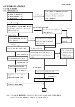
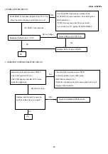
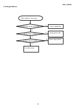
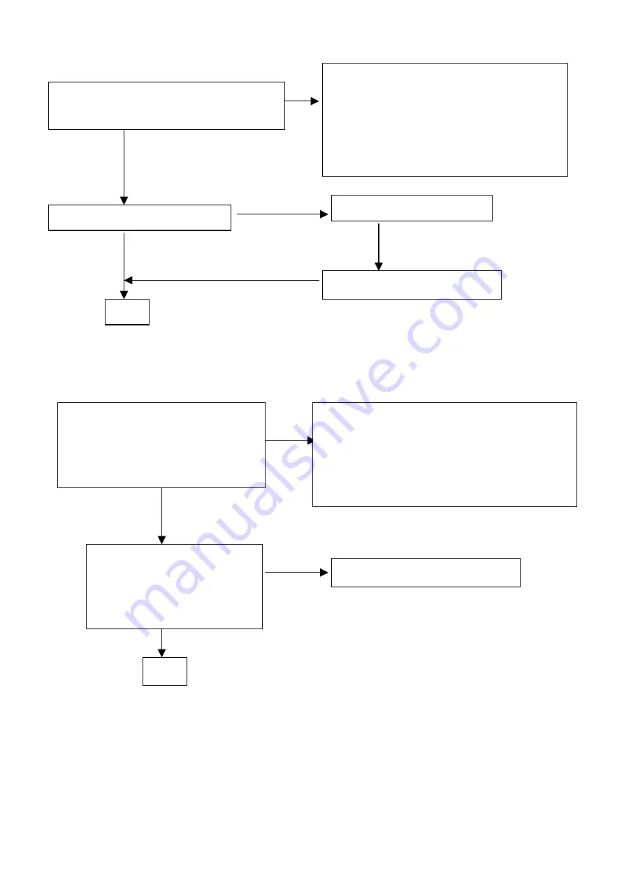
2.PANEL-POWER CIRCUIT
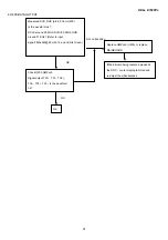
3. INVERTER CONTROL RELATIVE CIRCUIT
Check FB401 should have response from 0V to 3.3V
When we switch the power switch from on to off
NG
Check the PPWR panel power relative circuit,
Q300, Q303 In normal operation, when LED =green,
R308 should =0 v,
If PPWR no-response when the power switch
Turn on and turn off, replace the U200-GMZan3
OK, FB401 have response
NG, no Voltage
Measured the Q300 pin 2= 3.3 V?
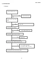
Check U202 pin 74,77,80=3.3V
OK
OK
Replace Q300 ( N-mos, AO3401)
Yes
Measured the inverter connector CN400
Pin1 on/off control=3.3V (on)
Pin2 PWM signal control dim 0V-5V when
adjust the brightness
NG
Check the Bklt-On relative circuit, R400,
In normal operation, when LED =green,
R400 Bklt-On should =3.3 v,
If Bklt-On no-response when the power switch turn on-off,
Replace U202 GmZAN3
NG, still no screen
Replace Inverter board to new-one,
and Check the screen is normal??
OK
NG
Check NO SCREEN APPEAR block
OK
Summary of Contents for E152FPc
Page 12: ...DELL E152FPc 12 4 4 3 OPTICAL CHARACTERISTICS ...
Page 13: ...DELL E152FPc 13 4 4 4 PARAMETER GUIDE LINE FOR CCFL INVERTER BACKLIGHT ...
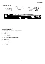
Page 14: ...DELL E152FPc 14 5 BLOCK DIAGRAM 5 1 MONITOR EXPLODED VIEW ...
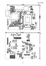
Page 24: ...DELL E152FPc 25 7 PCB LAYOUT 7 1 MAIN BOARD ...
Page 25: ...DELL E152FPc 26 ...
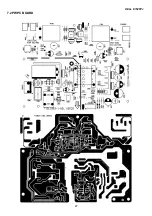
Page 26: ...DELL E152FPc 27 7 2 PWPC BOARD ...
Page 52: ...DELL E152FPc 53 12 DEFINITION OF PIXEL DEFECTS 12 1 VISUAL INSPECTION ...


