background image

4

Chapter 2

4.

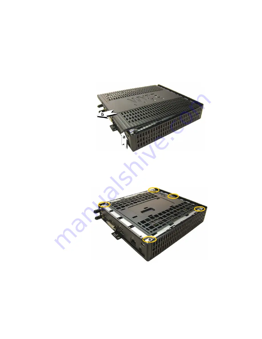
Place your thumbs on the top surface of the opposite end where the three screws 
were removed. With a continuous motion, push firmly downward and towards the 
back panel (pushing down unlatches the hooks under the cover). The cover will 
shift approximate 1/4 inch to hang over the back panel. 

(a) 

Grasp the overhanging 

cover edge and raise the edge about 1-1/2 inches, and then 

(b) 

pull the cover out 

towards the back panel at the same angle to free the opposite end of the cover from 
the remaining hooks, as shown in Figure 2.

Figure 2  Removing the cover

5.

Remove the cover to expose the main-board shield.

Figure 3  Main-board shield 

6.

Using the Phillips Screwdriver, remove the five screws from the main-board shield 
(four corner screws and one screw mid-way along the front edge). Remove the 
main-board shield and unplug the speaker wire (red wire) to expose the main board 
and Flash module as shown in Figure 4.

WARNING

: Flash modules may be susceptible to damage by Electro-Static 

Discharge (ESD). All industry-standard cautions should be followed to avoid ESD. 
Before you remove or install a module, touch any metal part of the chassis and keep 
that contact with the chassis during the installation process.

Summary of Contents for D90D7

Page 1: ...Installation Guide Dell Wyse D Class Wyse X Class and Wyse Z Class Flash Upgrade Option Kit Products D90D7 D90DW X90m7 X90mw Z90D7 Z90S7 Z90DE7 Z90DW Z90SW Issue 031214 PN 883884 31L Rev C ...

Page 2: ...ct you agree to be bound by those terms Trademarks The Dell and Wyse logos and Wyse are trademarks of Dell Inc Other product names mentioned herein are for identification purposes only and may be trademarks and or registered trademarks of their respective companies Specifications subject to change without notice You acknowledge that the Software is of U S origin You agree to comply with all applic...

Page 3: ... 2 2 Installing D Class Flash 3 Requirements 3 Procedures 3 3 Installing X Class Flash 7 Requirements 7 Procedures 7 4 Installing Z Class Flash 9 Requirements 9 Procedures 9 5 Installing Firmware 13 Requirements 13 Procedures 14 Troubleshooting 19 USB Keys Troubleshooting Boot Issues 19 SanDisk Cruiser Flash Drives Troubleshooting Partition Issues 19 ...

Page 4: ...iv Contents This page intentionally blank ...

Page 5: ...months of warranty of the thin client in which it is installed or for 90 days whichever is greater Installation of this kit will not void the factory warranty however the user will be responsible for damage due to improper installation Overview To upgrade flash 1 Perform a hardware installation install new flash by completing one of the following depending on your thin client class Installing D Cl...

Page 6: ...onal support visit http www wyse com global Related Documentation and Services Fact Sheets containing the features of hardware products are available on the Dell Web site Go to http www wyse com products and use the Cloud clients tab to locate and download the Fact Sheet for your hardware product Administrator and other documentation for your cloud client model are available at http www wyse com m...

Page 7: ...ION Follow all precautions listed in the Quick Start Guide that came with your thin client for disconnecting and reconnecting the thin client 1 Perform a proper shutdown of the thin client by closing all files and ending your session and then pressing the power button to turn off the thin client 2 Unplug the power cord and power adapter and remove any other cables from the thin client and detach t...

Page 8: ...g hooks as shown in Figure 2 Figure 2 Removing the cover 5 Remove the cover to expose the main board shield Figure 3 Main board shield 6 Using the Phillips Screwdriver remove the five screws from the main board shield four corner screws and one screw mid way along the front edge Remove the main board shield and unplug the speaker wire red wire to expose the main board and Flash module as shown in ...

Page 9: ... and the main board shield five screws 10 Replace the cover in the reverse order as described in step 4 align the cover screw tabs with the screw holes and slide the cover toward the front of the thin client 11 Attach the cover screws in the reverse order as described in step 3 12 Connect the power cord and power adapter attach any other cables to the thin client and then attach the vertical foot ...

Page 10: ...6 Chapter 2 This page intentionally blank ...

Page 11: ...orm a proper shutdown of the mobile thin client by closing all files and ending your session and then pressing the power button to turn off the mobile thin client 2 Unplug the power cord and power adapter and then remove any other cables from the mobile thin client 3 Position the mobile thin client to access the bottom cover and then remove the screws from the cover using a small Phillips screwdri...

Page 12: ...order of removing the original flash module Carefully screw down its retaining screw until it is secure 7 Replace the flash cover in the reverse order as described in steps 4 and 3 CAUTION Do not turn on the mobile thin client The mobile thin client is ready to re image however the flash module does not contain an operating system Turning on power to your mobile thin client without firmware will d...

Page 13: ...isted in the Quick Start Guide that came with your thin client for disconnecting and reconnecting the thin client 1 Perform a proper shutdown of the thin client by closing all files and ending your session and then pressing the power button to turn off the thin client 2 Unplug the power cord and power adapter and remove any other cables from the thin client and detach the vertical foot 3 Position ...

Page 14: ...raise the edge about 1 1 2 inches and then b pull the cover out towards the back panel at the same angle to free the opposite end of the cover from the remaining hooks as shown in Figure 10 Figure 10 Removing the cover 6 Remove the cover to expose the flash module as shown in Figure 11 WARNING Flash modules may be susceptible to damage by Electro Static Discharge ESD All industry standard cautions...

Page 15: ...er screw tabs with screw holes and press downward b slide cover toward the front of the thin client as shown in Figure 12 Figure 12 Reattaching the cover 10 Attach the screws in the reverse order as described in step 3 11 Connect the power cord and power adapter attach any other cables to the thin client and then attach the vertical foot CAUTION Do not turn on the thin client The thin client is re...

Page 16: ...12 Chapter 4 This page intentionally blank ...

Page 17: ... of the USB key onto these target devices containing your upgraded flash EXTREEMLY IMPORTANT You must perform the steps to create and use the configured USB key on each thin client as noted You cannot completely convert one thin client and then use the USB Firmware Tool to pull and push that image to your other thin clients Requirements Machine with a minimum of 16 GB of free space running either ...

Page 18: ...tract the firmware to the local hard drive folder you want D90D7 Only BDB0_0858_8192 exe D90DW Only ADA0_S727_2048 exe X90m7 Only BXB8_0858_8192 exe X90mw Only AXA8_S716_2048 exe Z90D7 Z90S7 and Z90DE7 Only BZB0_0858_8192 exe Z90DW and Z90SW Only AZA0_S723_2048 exe Step 2 Install Wyse USB Firmware Tool v1 20 0 1 1 Download the Wyse_USB_Firmware_Tool_v1 20 0 1 exe to a folder on your machine go to ...

Page 19: ... on the desktop for the Wyse USB Firmware Tool exe file and select Run as administrator to run the tool and open the Wyse USB Firmware Tool wizard the welcome page provides the product version and description and a link to view the Wyse end user license agreement Figure 13 Wyse USB Firmware Tool wizard 2 Click Next to open the Select an Option dialog box Figure 14 Configuration options 3 Select th...

Page 20: ...flash select one of the following OS type options D90DW X90mw Z90DW and Z90SW Only Windows Embedded Standard D90D7 X90m7 Z90D7 Z90S7 and Z90DE7 Only Windows Embedded Standard 7 5 Select the Update or Push Firmware operation to perform option Be sure that all three contents options are selected OS Image BIOS and CMOS 6 Clear uncheck the Preserve data partition check box 7 Click Next to open the bro...

Page 21: ...18 Prepare USB Drive 11 Select the USB key onto which you want the configurations you can use Refresh as needed to recognize an inserted USB key and then click Next The progress bars show the overall formatting and configuration progress and task progress CAUTION DO NOT interrupt the formatting and configuration process All process requirements are done automatically The progress screen may displa...

Page 22: ...option and press Enter Select the option displaying your USB key vendor name and move it to the 1 position by using the key Save the BIOS settings and reboot Follow the process prompts For Z90D7 Z90S7 Z90DW and Z90SW thin clients You must use the one time boot menu the one time boot menu will not modify your default BIOS configurations Be sure the client is shut down and disconnected from any netw...

Page 23: ...ls on U3 see http www u3 com When you initially use these drives you are prompted to select the use for the drive Apps and Storage or only Storage If you select the Apps and Storage option the drive will create two partitions one of which is identified as a CD and is a read only partition This partition sometimes prevents the Wyse USB Firmware Tool to properly prepare the USB key for imaging a dev...

Page 24: ...Installation Guide Dell Wyse D Class Wyse X Class and Wyse Z Class Flash Upgrade Option Kit Issue 031214 Written and published by Dell Inc March 2014 Created using FrameMaker and Acrobat ...

Reviews: