background image

Back to Contents Page


 Display Assembly  

Alienware

® 

M14x Service Manual  


Removing the Display Assembly 


Replacing the Display Assembly 


Removing the Display Assembly  


1.

Follow the instructions in 

Before You Begin

.  


2.

Remove the base cover (see 

Removing the Base Cover

).  


3.

Remove the battery pack (see 

Removing the Battery Pack

).  


4.

Disconnect the antenna cables from the Mini-Card(s)(see 

Removing the Mini-Card(s)

).  


5.

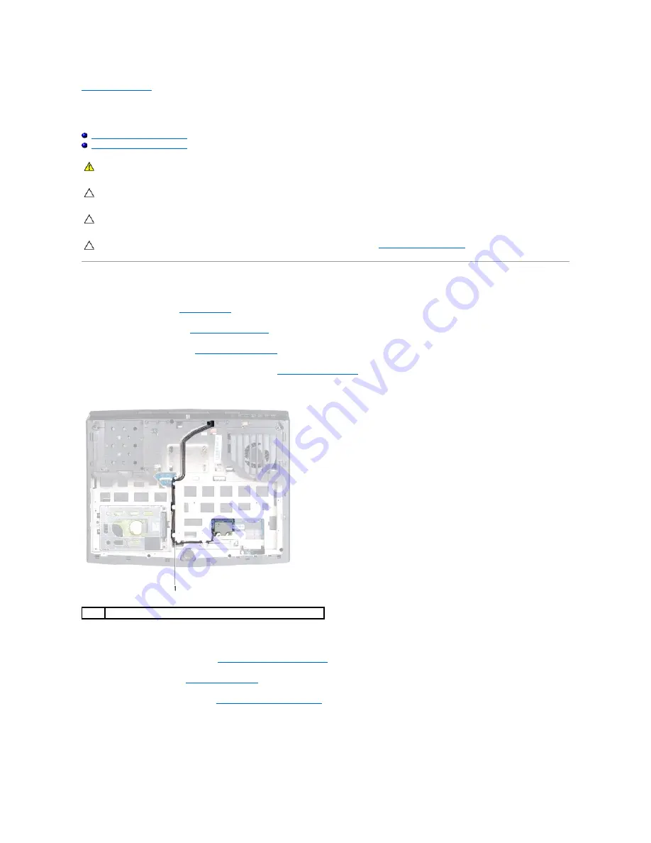
Note the routing of the Mini-Card antenna cables and remove them from the routing guides on the computer base.  


6.

Turn the computer over and open the display as far as possible.  


7.

Remove the center-control cover (see 

Removing the Center-Control Cover

).  


8.

Remove the keyboard (see 

Removing the Keyboard

).  


9.

Remove the palm-rest assembly (see 

Removing the Palm-Rest Assembly

).  


10.

Using the pull tab, disconnect the display cable from the connector on the system board.  


11.

Disconnect the touch-screen board cable from the connector on the system board.  


12.

Remove the four screws that secure the display assembly to the computer base.  


WARNING: 

Before working inside your computer, read the safety information that shipped with your computer. For additional safety best 

practices information, see the Regulatory Compliance Homepage at dell.com/regulatory_compliance. 


CAUTION: 

To avoid electrostatic discharge, ground yourself by using a wrist grounding strap or by periodically touching an unpainted metal 

surface (such as a connector on your computer).


CAUTION: 

Only a certified service technician should perform repairs on your computer. Damage due to servicing that is not authorized by Dell is 

not covered by your warranty.


CAUTION: 

To help prevent damage to the system board, remove the main battery (see 

Removing the Battery Pack

) before working inside the 

computer.

Mini-Card antenna cables 

Summary of Contents for Alienware M14x MOBILE

Page 1: ...d in this document to refer to either the entities claiming the marks and names or their products Dell Inc disclaims any proprietary interest in trademarks and trade names other than its own Regulatory model P18G Regulatory type P18G001 2011 02 Rev A00 Before You Begin Base Cover Battery Pack Optical Drive Hard Drive Memory Module s Center Control Cover Keyboard Palm Rest Assembly Wireless Mini Ca...

Page 2: ...eplacing the Base Cover Back to Contents Page WARNING Before working inside your computer read the safety information that shipped with your computer For additional safety best practices information see the Regulatory Compliance Homepage at dell com regulatory_compliance CAUTION To avoid electrostatic discharge ground yourself by using a wrist grounding strap or by periodically touching an unpaint...

Page 3: ......

Page 4: ...al damage and to help to ensure your own personal safety 1 Ensure that the work surface is flat and clean to prevent the computer cover from being scratched CAUTION To avoid losing data save and close all open files and exit all open programs before you turn off your computer WARNING Before working inside your computer read the safety information that shipped with your computer For additional safe...

Page 5: ...d service options Because availability varies by country and product some services may not be available in your area To contact Dell for sales technical support or customer service issues 1 Go to dell com contactdell 2 Select your country or region 3 Select the appropriate service or support link based on your need 4 Choose the method of contacting Dell that is convenient for you Back to Contents ...

Page 6: ...you are an expert computer user Certain changes can cause your computer to work incorrectly NOTE Keyboard failure may result when a key on the keyboard is held down for extended periods of time To avoid possible keyboard failure press and release F2 in even intervals until the System Setup screen appears NOTE If you wait too long and the operating system logo appears continue to wait until you see...

Page 7: ...the Performance Options sub menu for more information see Advanced Performance Options Menu SATA Operation Allows you to configure the operating mode of the integrated SATA hard drive controller l ATA SATA is configured for ATA mode l AHCI SATA is configured for AHCI mode SATA HARD DRIVE 1 Displays the installed SATA hard drive model Adapter Warnings Allows you to choose if the computer should dis...

Page 8: ...ng system l Enabled The internal WWAN device is enabled Wireless Switch Hotkey Allows you to disable all internal wireless devices Security Menu Supervisor Password Displays if the supervisor password is clear or set User Password Displays if the user password is clear or set Set Service Tag Displays the service tag of the computer when the service tag is present Displays a field to input the serv...

Page 9: ...into place 3 Tighten the two captive screws that secure the base cover to the computer base Back to Contents Page WARNING Before working inside your computer read the safety information that shipped with your computer For additional safety best practices information see the Regulatory Compliance Homepage at dell com regulatory_compliance CAUTION To avoid electrostatic discharge ground yourself by ...

Page 10: ...er base 9 Note the routing of Bluetooth card cable and remove the cable from the routing guides 10 Lift the Bluetooth card along with the cable off the computer base Replacing the Bluetooth Card WARNING Before working inside your computer read the safety information that shipped with your computer For additional safety best practices information see the Regulatory Compliance Homepage at dell com r...

Page 11: ...the palm rest assembly see Replacing the Palm Rest Assembly 6 Replace the keyboard see Replacing the Keyboard 7 Replace the center control cover see Replacing the Center Control Cover 8 Replace the battery pack see Replacing the Battery Pack 9 Replace the base cover see Replacing the Base Cover Back to Contents Page CAUTION Before turning on the computer replace all screws and ensure that no stray...

Page 12: ...ell battery and adhere it to slot on the computer base 3 Connect the coin cell battery cable to the connector on the system board 4 Replace the palm rest assembly see Replacing the Palm Rest Assembly WARNING Before working inside your computer read the safety information that shipped with your computer For additional safety best practices information see the Regulatory Compliance Homepage at dell ...

Page 13: ...trol Cover 7 Replace the battery pack see Replacing the Battery Pack 8 Replace the base cover see Replacing the Base Cover Back to Contents Page CAUTION Before turning on the computer replace all screws and ensure that no stray screws remain inside the computer Failure to do so may result in damage to the computer ...

Page 14: ... tab disconnect the display cable from the connector on the system board 11 Disconnect the touch screen board cable from the connector on the system board 12 Remove the four screws that secure the display assembly to the computer base WARNING Before working inside your computer read the safety information that shipped with your computer For additional safety best practices information see the Regu...

Page 15: ...uter over and route the Mini Card antenna cables through the routing guides on the computer base 7 Connect the Mini Card antenna cables to the Mini Card s see Replacing the Mini Card s 8 Replace the palm rest assembly see Replacing the Palm Rest Assembly 9 Replace the keyboard see Replacing the Keyboard 10 Replace the center control cover see Replacing the Center Control Cover 11 Replace the batte...

Page 16: ...an to the heat sink 4 Replace the three screws that secure the thermal fan to the system board 5 Connect the thermal fan cable to the connector on the system board WARNING Before working inside your computer read the safety information that shipped with your computer For additional safety best practices information see the Regulatory Compliance Homepage at www dell com regulatory_compliance CAUTIO...

Page 17: ... 5 to step 20 in Replacing the System Board Back to Contents Page CAUTION Before turning on the computer replace all screws and ensure that no stray screws remain inside the computer Failure to do so may result in damage to the computer ...

Page 18: ...e product model number in the Select Your Product Model list e Click Confirm 4 A list of results appear on the screen Click BIOS 5 Click Download Now to download the latest BIOS file The File Download window appears 6 Click Save to save the file on your desktop The file downloads to your desktop 7 Click Close if the Download Complete window appears The file icon appears on your desktop and is titl...

Page 19: ...TION To help prevent damage to the system board remove the main battery see Removing the Battery Pack before working inside the computer CAUTION To prevent data loss turn off your computer see Turning Off Your Computer before removing the hard drive assembly Do not remove the hard drive while the computer is On or in Sleep state CAUTION Hard drives are extremely fragile Exercise care when handling...

Page 20: ... to the computer base 8 Follow the instructions from step 7 to step 9 in Replacing the Optical Drive 9 Replace the battery pack see Replacing the Battery Pack 10 Replace the base cover see Replacing the Base Cover 11 Install the operating system for your computer as needed 12 Install the drivers and utilities for your computer as needed Back to Contents Page 3 pull tab 4 hard drive assembly 1 pull...

Page 21: ...al safety best practices information see the Regulatory Compliance Homepage at dell com regulatory_compliance WARNING If you remove the heat sink from the computer when the heat sink is hot do not touch the metal housing of the heat sink CAUTION Only a certified service technician should perform repairs on your computer Damage due to servicing that is not authorized by Dell is not covered by your ...

Page 22: ...Back to Contents Page ...

Page 23: ... rest assembly 7 Lift the center control cover off the computer base WARNING Before working inside your computer read the safety information that shipped with your computer For additional safety best practices information see the Regulatory Compliance Homepage at dell com regulatory_compliance CAUTION To avoid electrostatic discharge ground yourself by using a wrist grounding strap or by periodica...

Page 24: ...ose the display and turn the computer over 5 Replace the three screws that secure the center control cover to the computer base 6 Replace the battery pack see Replacing the Battery Pack 7 Replace the base cover see Replacing the Base Cover Back to Contents Page 1 center control cover CAUTION Before turning on the computer replace all screws and ensure that no stray screws remain inside the compute...

Page 25: ...system board Replacing the Mini Card Board 1 Follow the instructions in Before You Begin 2 Align the connector on the mini card board with the connector on the system board and press gently WARNING Before working inside your computer read the safety information that shipped with your computer For additional safety best practices information see the Regulatory Compliance Homepage at dell com regula...

Page 26: ...nter control cover see Replacing the Center Control Cover 7 Replace the Mini Card s see Replacing the Mini Card s 8 Replace the battery pack see Replacing the Battery Pack 9 Replace the base cover see Replacing the Base Cover Back to Contents Page CAUTION Before turning on the computer replace all screws and ensure that no stray screws remain inside the computer Failure to do so may result in dama...

Page 27: ... shipped with your computer For additional safety best practices information see the Regulatory Compliance Homepage at dell com regulatory_compliance CAUTION To avoid electrostatic discharge ground yourself by using a wrist grounding strap or by periodically touching an unpainted metal surface such as a connector on your computer CAUTION Only a certified service technician should perform repairs o...

Page 28: ...the keyboard to secure the keyboard under the tab on the palm rest assembly 5 Replace the three screws that secure the keyboard to the computer base 6 Replace the center control cover see Replacing the Center Control Cover 7 Replace the battery pack see Replacing the Battery Pack 8 Replace the base cover see Replacing the Base Cover Back to Contents Page 1 keyboard cable 2 backlit keyboard cable C...

Page 29: ...atus light board to the palm rest assembly 10 Lift the status light board along with its cable away from the palm rest assembly WARNING Before working inside your computer read the safety information that shipped with your computer For additional safety best practices information see the Regulatory Compliance Homepage at www dell com regulatory_compliance CAUTION To avoid electrostatic discharge g...

Page 30: ...assembly 5 Replace the palm rest assembly see Replacing the Palm Rest Assembly 6 Replace the keyboard see Replacing the Keyboard 7 Replace the center control cover see Replacing the Center Control Cover 8 Replace the battery pack see Replacing the Battery Pack 9 Replace the base cover see Replacing the Base Cover Back to Contents Page 1 status light board 2 screw CAUTION Before turning on the comp...

Page 31: ...ry module connector until the memory module pops up WARNING Before working inside your computer read the safety information that shipped with your computer For additional safety best practices information see the Regulatory Compliance Homepage at dell com regulatory_compliance CAUTION To avoid electrostatic discharge ground yourself by using a wrist grounding strap or by periodically touching an u...

Page 32: ...lace 5 Tighten the two captive screws that secure the memory module cover to the computer base 6 Replace the battery pack see Replacing the Battery Pack 7 Replace the base cover see Replacing the Base Cover 8 Turn on the computer 1 memory module connector 2 securing clips 2 3 memory module NOTE If you need to install memory modules in two connectors install a memory module in the lower connector b...

Page 33: ... detects the additional memory and automatically updates the system configuration information To confirm the amount of memory installed in the computer Click Start Control Panel System and Security System Back to Contents Page ...

Page 34: ...on that shipped with your computer For additional safety best practices information see the Regulatory Compliance Homepage at dell com regulatory_compliance CAUTION To avoid electrostatic discharge ground yourself by using a wrist grounding strap or by periodically touching an unpainted metal surface such as a connector on your computer CAUTION Only a certified service technician should perform re...

Page 35: ...ctive antistatic packaging For more information see Protecting Against Electrostatic Discharge in the safety information that shipped with your computer CAUTION Use firm and even pressure to slide the card into place If you use excessive force you may damage the connector CAUTION The connectors are keyed to ensure correct insertion If you feel resistance check the connectors on the card and on the...

Page 36: ...cable from the connector on the optical drive 9 Gently peel the optical drive cable from the optical drive bracket WARNING Before working inside your computer read the safety information that shipped with your computer For additional safety best practices information see the Regulatory Compliance Homepage at dell com regulatory_compliance CAUTION Only a certified service technician should perform ...

Page 37: ...ect the optical drive cable connector to the connector on the optical drive 6 Replace the two screws that secure the the optical drive cable to the optical drive 7 Align the captive screws on the optical drive with the screw holes on the computer base 8 Tighten the four captive screws that secure the optical drive to the computer base 9 Slide the optical drive cable into the connector on the syste...

Page 38: ...Back to Contents Page CAUTION Before turning on the computer replace all screws and ensure that no stray screws remain inside the computer Failure to do so may result in damage to the computer ...

Page 39: ...e palm rest assembly to the computer base 11 Carefully pry out the palm rest assembly along the rear edge and then ease the palm rest assembly from the computer base WARNING Before working inside your computer read the safety information that shipped with your computer For additional safety best practices information see the Regulatory Compliance Homepage at dell com regulatory_compliance CAUTION ...

Page 40: ...nnector latches to secure the cables 6 Replace the keyboard see Replacing the Keyboard 7 Replace the center control cover see Replacing the Center Control Cover 8 Close the display and turn the computer over 9 Replace the nine screws that secure the palm rest assembly to the computer base 10 Replace the battery pack see Replacing the Battery Pack 11 Replace the base cover see Replacing the Base Co...

Page 41: ...o avoid electrostatic discharge ground yourself by using a wrist grounding strap or by periodically touching an unpainted metal surface such as a connector on your computer CAUTION To help prevent damage to the system board remove the main battery see Removing the Battery Pack before working inside the computer CAUTION To prevent intermittent contact between the ZIF socket cam screw and the proces...

Page 42: ...o Contents Page NOTE If a new processor module is installed you will receive a new thermal cooling assembly which will include an affixed thermal pad or you will receive a new thermal pad along with documentation to illustrate proper installation NOTE The pin 1 corner of the processor module has a triangle that aligns with the triangle on the pin 1 corner of the ZIF socket CAUTION To avoid damage ...

Page 43: ...llow the instructions in Before You Begin 2 Slide the power button board cable through the slot on the palm rest assembly 3 Use the alignment posts on the palm rest assembly to place the power button board in place WARNING Before working inside your computer read the safety information that shipped with your computer For additional safety best practices information see the Regulatory Compliance Ho...

Page 44: ...place the keyboard see Replacing the Keyboard 8 Replace the center control cover see Replacing the Center Control Cover 9 Replace the battery pack see Replacing the Battery Pack 10 Replace the base cover see Replacing the Base Cover Back to Contents Page CAUTION Before turning on the computer replace all screws and ensure that no stray screws remain inside the computer Failure to do so may result ...

Page 45: ...bly 10 Lift the speakers along with its cable away from the palm rest assembly Replacing the Speakers WARNING Before working inside your computer read the safety information that shipped with your computer For additional safety best practices information see the Regulatory Compliance Homepage at dell com regulatory_compliance CAUTION To avoid electrostatic discharge ground yourself by using a wris...

Page 46: ...alm rest assembly see Replacing the Palm Rest Assembly 5 Replace the keyboard see Replacing the Keyboard 6 Replace the center control cover see Replacing the Center Control Cover 7 Replace the battery pack see Replacing the Battery Pack 8 Replace the base cover see Replacing the Base Cover Back to Contents Page CAUTION Before turning on the computer replace all screws and ensure that no stray scre...

Page 47: ...placing the Subwoofer 1 Follow the instructions in Before You Begin 2 Align the slots on the subwoofer with the alignment posts on the computer base WARNING Before working inside your computer read the safety information that shipped with your computer For additional safety best practices information see the Regulatory Compliance Homepage at dell com regulatory_compliance CAUTION To avoid electros...

Page 48: ...board see Replacing the Keyboard 7 Replace the center control cover see Replacing the Center Control Cover 8 Replace the battery pack see Replacing the Battery Pack 9 Replace the base cover see Replacing the Base Cover Back to Contents Page CAUTION Before turning on the computer replace all screws and ensure that no stray screws remain inside the computer Failure to do so may result in damage to t...

Page 49: ...he Mini Card Board 13 Using the pull tab disconnect the display cable from the connector on the system board 14 Disconnect the touch screen board cable Bluetooth card cable hard drive cable coin cell battery cable and subwoofer cable from the connectors on the system board 15 Remove the five screws that secure the system board to the computer base 16 Lift and ease the connectors on the system boar...

Page 50: ...ace it on the computer base 7 Replace the five screws that secure the system board to the computer base 8 Connect the touch screen board cable Bluetooth card cable hard drive cable coin cell battery cable and subwoofer cable to the respective system board connectors 9 Connect the display cable to the connector on the system board 10 Replace the Mini Card board see Replacing the Mini Card Board 11 ...

Page 51: ...he computer 22 Enter the service tag see Entering the Service Tag in the BIOS Entering the Service Tag in the BIOS 1 Ensure that the AC adapter is plugged in and that the main battery is installed properly 2 Turn on the computer 3 Press F2 during POST to enter the system setup program 4 Navigate to the security tab and enter the service tag in the Set Service Tag field Back to Contents Page CAUTIO...

Page 52: ...ks of Microsoft Corporation in the United States and or other countries Bluetooth is a registered trademark owned by Bluetooth SIG Inc and is used by Dell under license Other trademarks and trade names may be used in this document to refer to either the entities claiming the marks and names or their products Dell Inc disclaims any proprietary interest in trademarks and trade names other than its o...

Reviews: