


Next steps
1.
Install the main power interposer board
.
Installing the main power interposer board
Prerequisites
Follow the safety guidelines listed in
on page 66.
Steps
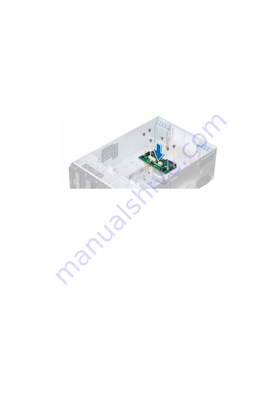
1. Align the screw holes on the main power interposer board (PIB) with the holes on the system chassis.
2. Using the Phillips #2 screwdriver, secure the main PIB to the system using the screws.
3. Connect all the disconnected power cables to the main PIB.
Figure 119. Installing the main power interposer board
Next steps
2.
.
3.
Install the power supply units
.
4. Follow the procedure listed in
After working inside your system
on page 67.
Converting the system from tower mode to rack mode
Your system can be converted from the tower mode to the rack mode.
To convert your system from the tower mode to the rack mode, you require the tower to rack conversion kit, which contains
the following:
●
Rack ears (left and right) with three screws each
●
VGA module
●
VGA cable
●
Rack slide cover
●
Mylar cover
Converting the system from tower mode to rack mode
Prerequisites
1. Follow the safety guidelines listed in
on page 66.
2. Follow the procedure listed in
Before working inside your system
160
Installing and removing system components
Summary of Contents for 5WC10
Page 21: ...Figure 16 Configuration and layout Dell EMC PowerEdge T640 overview 21 ...
Page 22: ...Figure 17 Electrical overview 22 Dell EMC PowerEdge T640 overview ...
Page 23: ...Figure 18 Memory information Dell EMC PowerEdge T640 overview 23 ...
Page 24: ...Figure 19 System tasks 24 Dell EMC PowerEdge T640 overview ...


