


Item
Control/Feature
Icon
Description
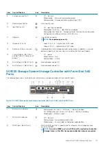
1
Battery status indicator
•
Blinking green (on 0.5 sec. / off 1.5 sec.) – Battery heartbeat
•
Fast blinking green (on 0.5 sec. / off 0.5 sec.) – Battery is charging
•
Steady green – Battery is ready
2
Battery fault indicator
•
Off – No faults
•
Blinking amber – Correctable fault detected
•
Steady amber – Uncorrectable fault detected; replace battery
3
MGMT port (Slot 3/Port 1)
—
Ethernet/iSCSI port that is typically used for storage system management and
access to the BMC
NOTE:
The MGMT port can be used as an iSCSI port for replication to
another Storage Center or as a front-end iSCSI port for connections to
host servers.
4
iSCSI port (Slot 3/Port 2)
—
Ethernet/iSCSI port that is typically used for replication to another Storage Center
(requires a replication license)
NOTE:
The iSCSI port can be used as a front-end port for connections to
host servers.
5
SAS activity indicators
—
There are four SAS PHYs per SAS port.
•
Off – SAS PHY is not connected
•
Steady green – SAS PHY is connected, but not active
•
Blinking green – SAS PHY is not connected nor active
6
Storage controller status
On – Storage controller completed a power-on self-test (POST)
7
Recessed power off button
Not currently used
8
Storage controller fault
•
Off – No faults
•
Steady amber – Firmware has detected an error
•
Blinking amber – Storage controller is performing a POST
9
Recessed reset button
Not currently used
10
Identification LED
•
Off – Identification disabled
•
Blinking blue (for 15 sec.) – Identification is enabled
•
Blinking blue (continuously) – Storage controller shut down to the Advanced
Configuration and Power Interface (ACPI) S5 state
11
USB port
One USB 3.0 connector
NOTE:
For engineering use only.
12
Diagnostic LEDs (8)
—
•
Green LEDs 0–3 – Low byte hex POST code
•
Green LEDs 4–7 – High byte hex POST code
13
Serial port (3.5 mm mini jack)
Used to perform initial storage controller configurations. In addition, it is used to
perform support only functions when instructed by Dell Technical Support.
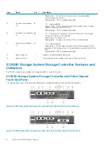
14
Two options:
•
Four Fibre Channel ports
(Slot 1/Port 1, Slot 1/Port 2,
Slot 1/Port 3, and Slot 1/
Port 4) with three LEDs per
port
•
Two Fibre Channel ports
(Slot 1/Port 1 and Slot 1/
Port 2) with three LEDs per
port
—
LEDs for the four 8 Gb Fibre Channel ports:
•
All off – No power
•
All on – Booting up
•
Blinking amber – 2 Gbps activity
•
Blinking green – 4 Gbps activity
•
Blinking yellow – 8 Gbps activity
•
Blinking amber and yellow – Beacon
•
All blinking (simultaneous) – Firmware initialized
•
All blinking (alternating) – Firmware fault
LEDs for the two 16 Gb Fibre Channel ports:
About the SC4020 Storage System
13


