3
Using the management software, prepare the drive for removal.
If the drive is online, the green activity or fault indicator flashes while the drive is turning off. When the drive indicators are off, the
drive is ready for removal. For more information, see the documentation for the storage controller.
CAUTION:
Before attempting to remove or install a drive while the system is running, see the documentation for the
storage controller card to ensure that the host adapter is configured correctly to support drive removal and insertion.
CAUTION:
Mixing drives from previous generations of PowerEdge servers is not supported.
CAUTION:
To prevent data loss, ensure that your operating system supports drive installation. See the documentation
supplied with your operating system.
Steps
1
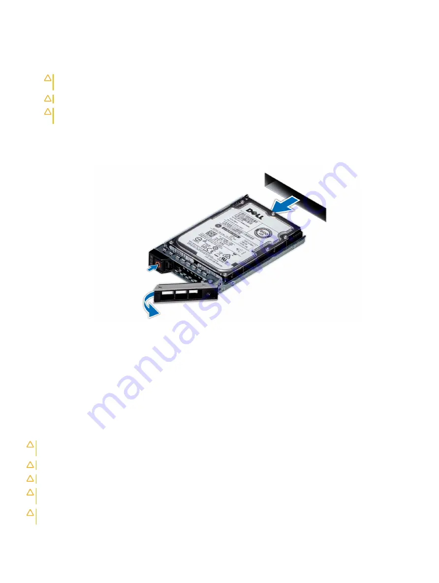
Press the release button to open the drive carrier release handle.
2
Holding the handle, slide the drive carrier out of the drive slot.
Figure 48. Removing a drive carrier
Next steps
1
2
If you are not replacing the drive immediately,
in the empty drive slot to maintain proper system cooling.
Installing a drive carrier
Prerequisites
CAUTION:
Before attempting to remove or install a drive while the system is running, see the documentation for the storage
controller card to ensure that the host adapter is configured correctly to support drive removal and insertion.
CAUTION:
Mixing drives from previous generations of PowerEdge servers is not supported.
CAUTION:
Combining SAS and SATA drives in the same RAID volume is not supported.
CAUTION:
When installing a drive, ensure that the adjacent drives are fully installed. Inserting a drive carrier and attempting to
lock its handle next to a partially installed carrier can damage the partially installed carrier's shield spring and make it unusable.
CAUTION:
To prevent data loss, ensure that your operating system supports hot-swap drive installation. See the documentation
supplied with your operating system.
94
Installing and removing system components
Summary of Contents for PowerEdge R740
Page 9: ...Figure 1 Supported configurations PowerEdge R740 system overview 9 ...
Page 28: ...Figure 22 NVDIMM battery and mid tray hard drives 28 PowerEdge R740 system overview ...
Page 141: ...Figure 94 Securing GPU 1 Installing and removing system components 141 ...
Page 142: ...Figure 95 Installing GPU 2 and 3 142 Installing and removing system components ...


