background image

Manual DEHLER 39  

36 - 72 


We set the thermostat on 90 º C. 


Look out 

Every year, you should retighten the hose braces. 

In case of frost risk, you have to drain the installation via the taps with the help of a 

pressure water pump and with the cold water tap opened. 


    FIGURE.: 

Fresh 

water 

distribution


4.3.2  Waste water pump 


We installed a JABSCO 37202 shower water suction pump.  With 12 l/min. the pump sucks 
more water as the water supply can supply.  If the water in the shower unit goes up, this 
means that the filter is clogged and should be cleaned.  You get easy access to it in the 
cupboard under the wash-basin.  The switch can be found on the port bulkhead wall. 
 

Summary of Contents for 39

Page 1: ...oat Shipyard Number HIN Hull Identification Number Design Category A OWNER S MANUAL DEHLER 39 Dehler Segelyachten GmbH Industriegebiet Im Langel D 59872 Meschede Telefon 0049 2903 440 0 Telefax 0049 2903 440 282 ...

Page 2: ...Manual DEHLER 39 2 72 Owner s manual version 28 08 01 Your Seller s Stamp ...

Page 3: ...2 4 Weights 16 2 5 Engine system 16 2 6 Electrical system 16 2 6 1 230 V Alternating current 16 2 6 2 12 V Direct current system 17 2 6 3 Battery capacities 17 2 7 Capacity of tanks 17 2 8 Maximum number of persons 17 2 9 Additional load 18 2 10 Cranes 18 3 General Drawings 19 3 1 2 Cab Version 19 3 2 3 Cab Version 20 3 3 Deck drawing 21 3 3 1 Deck 22 3 3 2 Sea railing 22 3 3 3 Lifeboat 22 3 4 Sai...

Page 4: ...4 5 2 Charge unit MASTERVOLT 38 4 6 On board direct current system 39 4 6 1 Setup of main fuses 39 4 6 2 Additional fuses 39 4 6 3 Main data switch board 41 Fuse locations 41 4 6 4 Battery Charging 42 Alternating current consumers 42 4 6 5 Auxiliary supply 42 4 6 6 Tank Control 42 4 6 7 Wiring diagram of switch board 43 4 6 8 Folded electric wiring diagram 44 4 6 9 Fuse bars Switch bars 45 4 6 10 ...

Page 5: ... space 58 6 Heating optional 59 6 1 Temperature control 59 6 3 Dosage pump Filter 59 7 Board outlets sea valves 60 7 1 2 Cab and 3 Cab Version 60 7 1 1 Cabin bilger 61 7 1 2 Helm hollow 61 7 1 3 Leak stop 61 Components 61 8 Environmental protection 63 8 1 Fuel and oil 63 8 2 Rubbish 63 8 4 Backwater 63 8 5 Exhaust fumes 63 8 6 Antifouling Paint 64 8 9 Paint remover 64 8 10 Holding tank optional 64...

Page 6: ...Ventilation 67 11 4 Rigging 67 11 5 Electricity 67 11 6 Hose braces 67 11 7 Tanks 68 11 8 Pump toilet 68 11 9 Paint 68 12 Winter storage 68 13 Final remarks and indications 69 14 Guarantee Card 71 15 Manufacturers Information 71 ...

Page 7: ...34 FIGURE HEAT EXCHANGER 35 FIGURE SHORE CONNECTION PANEL 38 FIGURE MAIN FUSES 39 FIGURE FUSE LOCATIONS FIGURE SWITCH BOARD 43 FIGURE WIRING DIAGRAM 43 FIGURE FUSE BARS 45 FIGURE BILGE SYSTEMS 48 FIGURE RUDDER SYSTEM 50 FIGURE EMERGENCY HEAD 51 FIGURE GAS SYSTEM 52 FIGURE SHUT OFF VALVE GAS 53 FIGURE HOLDING TANK SYSTEM 54 FIGURE FAST SHUT OFF VALVE SHOWER ROOM 55 FIGURE FIRE EXITINGUISHERS LOCATI...

Page 8: ...more about the handling and use of the yacht for your own safety and comfort before taking over the command Your seller is there to help you with everything you need Of course a prerequisite for a successful sailing trip is that you have sufficient experience as a sailor so that you know how to behave in all kinds of situations We hope you will enjoy your new DEHLER 39 and wish you good luck and s...

Page 9: ...e Gas Oven Sticker under the cooker s lid Main switch Engine Indication next to the companion way bow Main switch Consumption Indication next to the companion way bow Emergency shut off valve Fuel Diesel engine Sticker in the space under the navigation table above the reach through opening Only switch with neutral number of revolutions Sticker next to the Gas Switch Cold resistant Please observe m...

Page 10: ...ker next to the switch on the shore connection panel When sailing close the sea valves Sticker on each cupboard door and on the flap door hiding the sea valves Indication for the escape hatch Sticker on t he bow bulkhead on the bow hull Position crane belt Four stickers on deck side Warnings Gas Installation Sticker behind the bulkhead for the gas bottle FIGURE WARNINGS ...

Page 11: ...s to be tested by a recognized testing institute The Germanische Lloyd Abbreviation GL one of the testing institutes allowed by the EC Directive was in charge of testing see the Statement of Conformity on page 12 On the mirror on the fore castle the hull identification number was stamped in a gel coating This is a world wide unique succession of numbers and letters For example DEDEH 65012K900 This...

Page 12: ... This weight indication comprises persons supplies food supplies water fuel and personal equipment Max Pers Maximum number of persons recommended by the manufacturer when the boat is located in a maritime area corresponding to its design category Max kg Maximum weight of personal equipment 0098 CE Sign indicating that the boat was built accordin to the requirements of the Directive The succession ...

Page 13: ... Sailing yacht Type of Boat Dehler 39 Main dimensions 11 80 x 3 85 x 1 98 m or 11 80 x 3 85 x 2 35 m Serial number of hull see entry on the covering plate Design Category A Certification module Aa Applicable Directives EC RL Pleasure Craft 94 25 Ec Applied harmonized standards see Annex Page 13 Applied international standards see Annex Page 13 Applied national standards see Annex Page13 Other appl...

Page 14: ...looding Cockpit Cockpit drainage ISO CD 11812 Bilge system ISO WD 15083 3 6 Recommended maximum load ISO WD 14946 3 7 Storage space for lifeboats 3 8 Emergency escape fire protection ISO DIS 9094 3 9 Anchoring mooring towing ISO WD 15084 4 Engine power manoeuvring capacity ISO CD 11592 5 1 Engine system and engine room Steam noise heat ICOMIA Standard in preparation Ventilation ISO 11105 Petrol Ex...

Page 15: ...t HT 4 02 m Transport height regatta keel without support Hr 4 39 m Full height mast HD 18 30 m Full height mast with additional antennas Hmax D The full height can be critical when you have to pass undr a bridge or a high voltage line It is the height above the waterline until the highest point of the mast It is measured without possible antennas nor a radar reflector but taking into account the ...

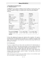
Page 16: ...l from 34 7 till 115 m 2 4 Weights Weight without load Standard keel Gempty 7 800 kg Weight without load Regatta keel Gempty 7 150 kg Max weight with standard keel Vmax approx 9 800 kg Max weight With Regatta keel Vmax approx 9 150 kg Keel weight standard keel Gs 2 945 kg Keel weight regatta keel Gs 2 295 kg 2 5 Engine system Manufacturer YANMAR Type 3GM30 FC 27 hp Optional 3JH3CE 40 hp 2 6 Electr...

Page 17: ...l The tank is installed in the cabin under the starboard side berth 1 stanless steel holding tank optional 45 l The tank is installed on starboard in the closet of the shower room rear cabin 1 stanless steel holding tank 45 l incl in second shower room To see a detailed description of the different water tanks see installation schemes on the next pages 2 8 Maximum number of persons The Directive r...

Page 18: ... are taken on land with a crane and hoisting gear Belts are to be placed taking into account the solidity of the boat s build and the distribution of weight On the Dehler 39 the recommended bearances are marked on the coaming guard rods The bearance at the front is A at about 4 00 m of the bow front and the bearance at the rear is B at about 3 00 m of the stern side The distance C between these tw...

Page 19: ...Manual DEHLER 39 19 72 3 General Drawings 3 1 2 Cab Version FIGURE GENERAL DRAWING 2 CAB ...

Page 20: ... 4 Bow cupboard 5 Water tank 6 Cabin couch 7 Storage closets 8 Cool box 9 Double sink 10 Gas cooker 11 Cupboard 12 Batteries 13 Fuel tank 14 Navigation room 15 Shower room 16 Shower 2 Cab 17 Storage space 2 Cab 18 Stern berths 19 Heating 20 Storage space stern 21 Heat exchanger FIGURE Genera ldrawing 3 Cab ...

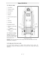
Page 21: ...inplate port 10 Shroud chainplate stern 11 Cabin hatch 12 Genua slide 13 Deck ventilator 14 Spring notches 15 Lever clamps 16 Waste water tank Suction cap 17 Halyard winches 18 Genua winches 19 Traveller 20 Spinnaker winches or main sheet 21 Steering column 22 Helm FIGURE DECK DRAWING 23 Gas tank 24 Rear notches 25 Backstay chainplates 26 Storage space cover 27 Foldable helmsman s seat with space ...

Page 22: ...ewed on the aluminium deck reinforcement and glued with epoxy resin Cleaning and Maintenance Hints Stainless steel Fittings Polish matt or dark areas so that the stainless steel keeps its anti corrosion characteristics Winches Blocks Dismount at least for winter storage cleaning and treatment with appropriate lubricants Windows hatch panes Wash with clean water and polish with a soft cloth Teak wo...

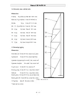
Page 23: ...are available to set spinnaker and other windsails 3 4 1 Sail dimensions P 14 90 E 5 40 I 15 70 J 4 40 FIGURE SAIL RIB With these data every sailmaker can make the sail you wish 3 4 2 Masting plan The mast is placed in a mast rail under the deck Mast length 18 44 m Boom length 5 60 m Length sailing arms from top to bottom 67 0 cm 101 1cm and 117 6 cm The profile measures for the SPARCRAFT rigging ...

Page 24: ...t running Standard Mainsheethaul 1 4 1 8 If you pull both ends of sheet it is1 4 If you pull only one end it is 1 8 FIGURE Halyard running Optional With optional mainsheet winches one part of the sheet is fastened at each winch Needed power is devided 1 2 3 4 5 Furling genua Main sheet traveller As an option the three furlings can be adjusted without graduation from the cockpit The adjustable top ...

Page 25: ...mm V1 Type Dyform 10mm Ø 4713 mm 3 7 Running rigging Dimensions Main halyard 10 mm Ø 38m colour neon green Jig halyard 10 mm Ø 35m colour light blue Spinnaker halyard top12 mm Ø 39m colour red Spinnaker halyard 10 mm Ø 34m colour red Top shroud 12 mm Ø 13m colour red Kicking strap 12 mm Ø 13 m colour blue white Outhaul 12 mm Ø 13 m colour blue white Reefing line I 10 mm Ø 21 5m colour blue white R...

Page 26: ...sail with a lubricant If the mast or the boom show damaged parts these should be cleaned and painted with a transparent varnish appropriate for aluminium Dark or rusty areas on the stainless steel fittings should be polished so that their quality characteristics remain With an extendible mast there is always the risk of having a leak at the mast gasket Additional sealing of joint between mast prof...

Page 27: ...tallation the engine room s partition walls are insulated The engine is accessible through the bulkhead behind the companion way In addition you can open a flap door in the shower room and in the rear cabin to get access to all relevant components of the engine After removing the rear wall flap door in the rear cabin you get access to the oil measuring rod of the gear 4 1 1 Exhaust system The yach...

Page 28: ...ntenance The seawater cooled exhaust system with water collector exhaust pipe and swan neck is cold resistant and does not need drainage The hose braces should be retightened once a year In winter the diesel engine should be made cold resistant We recommend to place a longer suction hose on the suction snouts of the water pump see YANMAR manual to prepare an antifreeze mix in a bucket and let the ...

Page 29: ...tensive manufacturer s information 4 1 5 Fuel tank A 110 l stainless steel diesel tank is installed under the starboard side cabin It gets filed through the deck screw on the main deck at the starboard front Inscription FUEL and Symbol Supply of and return to the on board diesel engine occurs through a fixed copper pipe and at the ends with fireproof fuel hoses pursuant to ISO 7840 Off board venti...

Page 30: ...Pump heating 7 Filter Water condenser 8 Suction pipe 9 Diesel pipe Heating 10 On board diesel engine 11 Fast shut off valve FIGURE FUEL PIPE SYSTEM LOOK OUT A perfect running of the engine is only possible with a clean fuel Therefore it is absolutely necessary to regularly check and clean the filter and water condenser ...

Page 31: ... When filling the tank always put off the engine heating and cooker When filling do not smoke Never handle with open fire Look out If a fire risk exists shut the safety valve behind the tank you get access to it in the space under the navigation table ...

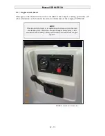
Page 32: ...guard rods All other information can be found in the extensive information of the company YANMAR HINT The one switch circuit is a combination between a circuit and an accelerating lever Between the gear changes always stay a few seconds in idle running Delayed switching avoids expensive gear repairs FIGURE ENGINE SWITCH BOARD ...

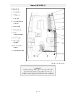
Page 33: ... side wall 4 2 2 Shower in the shower room near to the companion way The shower spray head is at the same time the tap for the wash basin The installation is completed by a filter and a suction pump with a separate outlet valve Both parts are installed in the closet under the wash basin Components 1 Checking cover with transmitter cylinder for tank indication 2 Polyurethane water tank 3 Pressure w...

Page 34: ...ter supply Engine return 11 Heat exchanger FIGURE HOT WATER 12 Drainage pipe heat exchanger From time to time you should replace the water in the tank In addition you can add commercial water treatment products for example Micropur to the water The engine two circuit cooling gets used once as heat source Since the engine is only foreseen to be used in calm weather and for manoeuvring in harbours t...

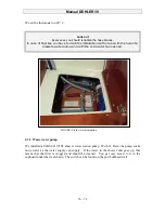
Page 35: ...friendly The sketch shows you the construction When normally running the valves are set as shown In case you need to drain the heat exchanger the valve 4 of the water tank has to be closed as well as the cold water inlet valve 6 Then you should open the ventilation valve 12 on the heat exchanger and finally the valve 5 of the suction pipe of the heat exchanger If you open the sink s cold water val...

Page 36: ...d with the cold water tap opened FIGURE Fresh water distribution 4 3 2 Waste water pump We installed a JABSCO 37202 shower water suction pump With 12 l min the pump sucks more water as the water supply can supply If the water in the shower unit goes up this means that the filter is clogged and should be cleaned You get easy access to it in the cupboard under the wash basin The switch can be found ...

Page 37: ...In case of repair the single water cycles can be closed through the closing of the fast shut off valves in order to replace for example the pressure water pump IMPORTANT Please observe the indications of SIGMA for maintenance and replacement of thermostat and heating element ...

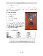
Page 38: ...ch Net control light On off switch heat exchanger with control light 230 V safety plug Charging of the battery starts once the shore connection cable gets plugged in The three 230 V plugs are all ready They are only there for power consumers Please think about the limited watt power of land plugs The outlet towards the hot water heating in the heat exchanger has a fixed cabling which is separately...

Page 39: ...e room According to the boat s equipment you will find up to seven fuses FIGURE MAIN FUSES 1 Electric halyard winch deck 2 Electric starbord genua winch 3 Electric starboard main sheet winch 4 Anchor winch 5 General consumers 6 Electric port side main sheet winch 7 Electric port side genua winch Further distribution to the general consumers is done via the power circuit distributor switch board ab...

Page 40: ...Bow and stern light Port side interior lighting tank Top light Starboard interior lighting Three colour light FM Radio Waste water tank Anchor light Navigation lighting sails Refrigerator Navigation instruments Automatic pilot system Water pump Interior light middle 12 V Plug Bilge pump Free ...

Page 41: ...ol lights to see if a switch circuit is switched on You should regularly check the navigation lights Direct current consumers The main circuits are the following Navigation lights Refrigeration unit for cool box Water pumps Engine instruments Tank indicator FM Radio Car radio Electronic navigation instruments Comfort consumers Bilge pumps Shower Bilge Anchor winch Automatic pilot system FIGURE FUS...

Page 42: ...tt power of shore connections is mostly limited Max 600 800 Watt 4 6 5 Auxiliary supply Navigation lighting should have absolute priority In case there is a capacity bottleneck caused by a technical fault in the supply all other consumers should first be switched off The running of the machine even when sailing can recharge the batteries which enables you to switch on the second most important con...

Page 43: ...ng diagram of switch board FIGURE WIRING DIAGRAM Sämtliche 12V Leitungen vom Panel 428 zur Verteilertafel 4281 werden jeweils mit der ent sprechenden Nummer oder Bezeichnung auf der Verteiler tafel verbunden 20 20 30 30 40 10 10 0 40 D ...

Page 44: ...Manual DEHLER 39 44 72 4 6 8 Folded electric wiring diagram Electriic wiring diagram Reverse ...

Page 45: ...BS cover you get access to the switch bar Nº 3 4 Switch bar back railing starboard We installed switch bar Nº 4 at the board wall before the construction iron support below 5 Switch bar settee Switch bar No 5 is installed under the quilting at the rear end of the tank 6 Switch bar closet room After dismounting the cover shelf above the closet you get access to the switch bar No 6 7 Fuse bar naviga...

Page 46: ...ugs All lamps have a built in switch so that a correct energy use is possible 4 6 13 Electric wiring diagram The wiring diagram helps when looking for faults Specialists know the switch signs and switch abbreviations used according to DIN standards which nowadays are used internationally Try to get used to the most important symbols with the help of an expert 4 6 14 Relevant indications for the di...

Page 47: ... power circuit Relevant indications for the alternating current system WARNING In order to avoid the risk of electrocution or fire never hang the shore connection cable in the water first connect the shore connection cable on board and then on land don t change the shore connection plugs Adapters for example in Denmark should be left on board Repairs on the 230 V installation should always be carr...

Page 48: ...ump 3 Return check valve 4 Bilge pipe E Bilge pump 5 Bilge pipe mechanical pump 6 Mechaniical pump 7 Outlet mechanical pump 8 Outlet electric pump 4 7 3 Hand bilge pump The suction filter is installed under the cabin table in the bilge 1 A return check valve avoids the return of the sucked bilge water Through a flexible hose it gets to the Whale hand bilge pump with a capacity of 90 l min mounted ...

Page 49: ...mp with a capacity of 90 l min the suction filter 2 is placed under the rear cabin couch The outlet is placed at the rear of the starboard cockpit You ll find the switch amongst the group of switches on the navigation panel WARNING The total pump capacity will probably not be sufficient to bilge the boat in case of a collision with floating objects Take your measures for such exceptional events th...

Page 50: ...ion is highly sensitive and direct The rudder is held by a rudder calking ring supported by a bearing in the rudder hole In addition the rudder shaft gets sealed through a shaft joint in the rudder hole FIGURE RUDDER SYSTEM Components 1 Steering column base 2 Rudder lever 3 Transmission lever 4 Return bearing 5 Rudder quadrant 6 Rudder shaft 7 Lower bearing 8 Rudder hed 9 Rudder fittings 10 Rudder...

Page 51: ...e The rudder practically does not need any maintenance Every five years you should dismount the rudder and carefully clean grease and reinstall the bearing surfaces Take care that the rudder can only be pulled in a crane or over a depression after loosening the rudder calking ring Every year you should check the tightening of the counter nuts of the tramsmission lever and of the rudder quadrant sc...

Page 52: ...ations need to be handled carefully Therefore you should keep to the following order Open the shut off valve in the bottle hollow in the port cockpit Open the valve in the cupboard for the cooker Push on one of the burner valves and light the gas FIGURE GAS INSTALLATION Keep the valve opened until the pilot flame allows further burning LOOK OUT When switching off always observe the following order...

Page 53: ...ion Have the closing screw at hand Don t use the gas bottle hollow to store other equipment parts Don t leave the yacht without supervision when the cooking stove is working Regularly check the hose pipes of the liquid gas installation at least once a year Replace them if they are damaged If you want to replace the cooker take care that the new cooker has the same working pressure 4 9 1 Certificat...

Page 54: ...necessary so that the ventilation pipe does nor get clogged If possible the tank should be sucked at every waste water pump station or only exceptionally be emptied outside of bays or harbours normally when you are sailing with the engine Therefore you should open the discharge valve 4 10 2 Emptying of the tank Where waste water pump stations are available the tank contents should be sucked off th...

Page 55: ...4 x during the season according to the frequency of use up to a third with sea water and a small amount of detergent and then go on sailing for a few hours The rubber valves stay soft and the tanks gets cleansed FIGURE FAST SHUT OFF VALVE SHOWER ROOM 4 1 4 Fast shut off valves According to the yacht s equipment you will find the following fast shut off valves in the shower room closet 1 Toilet sea...

Page 56: ...inflammable material in the engine room If you store non inflammable materials in the engine room take care that they cannot fall into the machines and that they don t hinder the access to the machines You yourself and your crew can contribute to a preventive fire protection by complying with the following instructions Never Close the ways to the exits and hatches Close the access to safety device...

Page 57: ...PG2 13A89B Nr 2 Foam fire extinguisher in the locker at the front bulkhead wall on starboard Fire category PG2 13A 89B Nr 3 HINT Under the second companion way step you ll find an opening In case of fire a fire in the engine room can be extinguished through this opening FIGURE FIRE EXTINGUISHER LOCATIONS Remove grey closing valve put the snout of the fire extinguisher into the opening HINT In addi...

Page 58: ...all opening Just place the snout of the fire extinguisher into this hole and empty the fire extinguisher completely Wait a few minutes before opening the engine room to check the damage 5 6 In case of a fire in the living space Here too the fire extinguisking ceiling can serve You should always have a piston pump in the equipment locker to activate the foam fire extinguisher in emergencies Relevan...

Page 59: ... rear cabin and shower room The quantity of air can be adjusted on all hot air outlets except in the cabin 6 1 Temperature control The control element got installed on the navigation panel The heating can be adjusted without phases The thermostat is installed on the navigation bulkhead on the upper left part Air distribution of the diesel heating 1 Hot air outlet bow 2 Hot air pipes 3 Hot air outl...

Page 60: ...ose side of each valve Each hose pipe is tightened by two braces List of board outlets 2 Cab and 3 Cab distribution 1 Board outlet 2 for log 2 Board outlet 2 for echosounder 3 Board outlet with ball valve Discharge wash basin 4 Board outlet with ball valve Supply toilet 5 Board outlet 1 with ball valve discharge holding tank or direct toilet 6 Board outlet with ball valve Discharge shower 7 Board ...

Page 61: ...damaged sea valve or board outlet your Dehler 39 is equipped with several leak stops made of soft wood whose diameters are fitted on the different sizes of the board outlets able to close every possible opening Components See the explanation on page 60 FIGURE BOARD OUTLETS 3 CAB Look out Close the ball valves when you leave the boat Ball valves in closed spaces for example toilets should only be o...

Page 62: ...Every year board outlets should be checked for electrolysis In case of damage install new board outlets Replacement should be carried out by a specialized firm Hint In case of ball taps you can easily see if they are closed or open CLOSED diagonal setting of the lever towards the hose or pipe OPEN the lever is set in the same direction as the hose or pipe ...

Page 63: ... should be evacuated together with the used oil In any case on board you should have oil binders 8 2 Rubbish Rubbish does not belong into the water every fan of water sports agrees This goes as well for biologically degradable rubbish On your boat you should have a fixed place for rubbish which you should collect and evacuate separately 8 3 Noise A wet exhaust of a diesel engine equipped with a si...

Page 64: ...pecial rubbish If you want to protect the hull under the waterline with epoxy barrier and antifouling follow the description of the manufactor of the used material 8 9 Paint remover Most paint removers are very aggresive and if possible should therefore not be used Mechanical removal of the paint layers for example with a scraper should be preferred above all other methods 8 10 Holding tank option...

Page 65: ...5 kg anchor chain and anchor line You should choose another anchor with a great holding power for example a Danforth anchor which can be stored safely in the equipment locker 9 3 Tie up rope 2 ropes Ø 16 mm 18 m long Polyamide 2 ropes Ø 16 mm 12 m long Polyamide This rope type can be replaced with other materials with a bigger diameter that is say with Polyester 18 mm Ø or polypropylene with a dia...

Page 66: ... where you cannot damage anything 6 Even on land don t go too near to reed beds and other densely covered areas so as not to disturb and endanger the living space of birds fishes small animals and plants 7 Obser ve and take photographs of animals from as far as possible 8 If you are in a mud flats area don t go near to seal banks so as not to disturb or drive away the animals Keep a distance of at...

Page 67: ...tion with their treatment and painting systems For boats sailing in salt water areas Salt rests bind the water and accelerate corrosion Where possible wash the boat with freshwater 11 3 Ventilation It doesn t matter if your boat is stored under roof or in the open air during winter A correct ventilation avoids corrosion mold stains and fungi With clear weather the low air humidity in winter quickl...

Page 68: ... parts As an experienced skipper you won t have any trouble to find original spare parts If you need some hints please ask your seller In case you need spare parts and the original parts are not available then you should pay attention to the solidity of the available parts to keep the Dehler 39 on the same technical level as at the beginning Repairs Every specialized company can repair the hull Th...

Page 69: ...gencies often do not have any problems But just in case you find yourself in the midst of an emergency be assured that your yacht is equipped with the right aids Finally we d like to give you some useful addresses Boatmakers Federation In case you need a shipyard for renovation or extension repairs storage or other services like for example the appointment of an expert please direct yourself to De...

Page 70: ...l DEHLER 39 70 72 Wasser und Schiffahrtsdirektion Südwest Brucknerstr 2 55127 Mainz Tel 06131 9 79 0 Fax 9 79 155 Wasser und Schiffahrtsdirektion Süd Wörthstr 19 97082 Würzburg Tel 0931 41 05 0 Fax 41 05 380 ...

Page 71: ...h your seller you will get the costs reimbursed pursuant to the normal rates of the sector in Germany If our service personnel carries out the repairs we will take charge of their travel costs All other claims are excluded except when there exists a legal liability obligation Our extended guarantee even covers faults caused by an incorrect treatment or excessive use These include bleaching and cra...

Page 72: ...DK Kolding Gas cooker LT 30 D User s and Maintenance manual Fa Triton Belco 22081 Hamburg Navigation lights Aquasignal Installation instructions Test certificate Fa Aquasignal 28307 Bremen Navigation instruments Autopilot systems Log Echosounder Raytheon Raytheon Raytheon Installtion and User s Manual Holland Nautic NL 7332 NZ Apeldoorn Battery charging devices Mastervolt Installation and User s M...

Reviews: