background image

SP500-C

4  

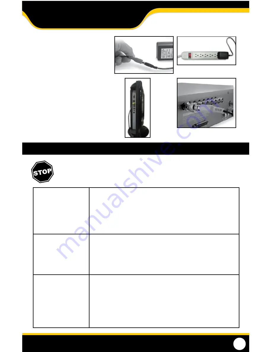
3.  Plug the camera’s power supply cord 

into the red power jack located on 

the 60ft video/power wire.

4.  Plug the camera’s power adapter into 

an AC outlet.

5.  Connect the 60ft video/power wire’s  

RCA plug (yellow) to the VIDEO IN 

port of your TV/monitor/ 


VCR/DVR. 

6.   If your VIDEO IN port is a BNC 

connection (common with DVR 

units), you will need to attach the 

BNC to RCA adapter (included) 

before connecting the camera.

3

4

6

  TROUBLESHOOTING

Before contacting technical support, please follow the troubleshooting tips below for solutions to  

common issues

No picture/signal: 

•  Make sure your TV/monitor is on the correct video input channel. This is NOT 

channel 3 Common terms for this channel is INPUT, AV   CHANNEL, LINE 1, LINE 

2 and AUX. Please use your TV or VCR manual to correctly identify this channel

•  If your camera is connected to a VCR/DVR, make sure that the VCR/DVR is 

properly connected to your TV/monitor

•  Check all connections to make sure they are secure and properly connected

•     Check your power supply to ensure that the camera is powered up

Picture is too bright:

•  Make sure your camera is not aimed at direct sunlight

•  Adjust the sunshade by sliding it forwards to block out excess light

•  Make sure nothing is obstructing the CDS sensor on the camera. If the CDS 

sensor is blocked, night vision mode will be active and may produce extra light 

in your camera’s picture

•  Move your camera to another location

Picture is too dark:

•  If using at night, make sure your camera’s subject is no more than 50ft away 

from area being monitored (may vary based on amount of light available)

•  If using during the day, your camera may not be getting enough light. Adjust 

the sunshade by sliding it backwards to let more light in

•  Check the brightness and contrast settings on your TV/monitor

•  If your camera is connected to a VCR/DVR, check the brightness and contrast 

settings on the VCR/DVR

•  Move your camera to another location

5

SETUP

Summary of Contents for SP500-C

Page 1: ...INSTRUCTION MANUAL V1 0 SP500 C www defender usa com Security Camera Indoor Outdoor Color Camera w NightVision...

Page 2: ...t features specifications or if you need any help with set up we are available 24 7 Pleasecontactusviaoneofthemethodsbelow Toll free telephone 1 866 946 7828 For more product information visit www Def...

Page 3: ...epair replacement or refund of the purchase price at Defender s option 2 This warranty becomes void if the product shows evidence of having been misused mishandled or tampered with contrary to the app...

Page 4: ...r purchase of the SP500 C enhanced night vision CCD camera This camera has 420 lines of resolution which work to provide you with a full color and incredibly clear picture This allows for a farther vi...

Page 5: ...the dark it must have objects for the LEDs to reflect off of in order to see them So ensure that the camera is pointed at actual objects within range and not at open areas Ensure that the sunshade is...

Page 6: ...provided drilling template see back of manual drill the proper holes and place the provided wall anchors into each hole 2 Mount the camera in the selected location by screwing the provided screws int...

Page 7: ...CR DVR is properly connected to yourTV monitor Check all connections to make sure they are secure and properly connected Check your power supply to ensure that the camera is powered up Picture is too...

Page 8: ...IR Cut Filter No Housing Material Anodized Aluminum Housing Color Black Signal Noise Ratio 48dB Camera Bracket Yes Lens Mount type M12 OperatingTemperature 14 F 122 F Operating Humidity 98 Camera Powe...

Page 9: ...ess Postal Code Phone Number Email Model Number of Product Serial Number of Product Purchase Date Place of Purchase NOTE We recommend that you keep a record of your purchase receipt with your manual f...

Page 10: ...00 C 7 DRILL HOLES IN SELECTED AREAS Towallmountthecamera drillthreeholesusinga3 16 drillbitandthetemplatebelow Insertsuppliedwallanchorsintoholesandsecurecameratowallwithsuppliedscrews DRILLINGTEMPLA...

Page 11: ...liable in any way shape or form for any damage vandalism theft or any other action that may occur while a Defender product is in use by the consumer VISIT US ONTHEWEB Product Information User Manuals...

Reviews: