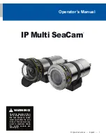
DeepSea Power & Light IP Multi SeaCam IPMSC-3070 Operator'S Manual Download Page 6

6

IP Multi SeaCam

®

Maintenance and Repair

Flooding Repair Procedure

If the camera stops working while underwater, assume 

that it has flooded. When working on a potentially 

flooded camera, use appropriate personal protective 

equipment to protect hands, body, and eyes.

1. 

Immediately turn off the power to the unit.

2.  Open the housing by removing the rear-end 


cap-retaining ring.

3.  Separate the two components by gently pulling 

them apart. If necessary, lightly twist components 

while separating.

4.  Pour out any water trapped in the housing.
5. 

If  the  camera  is  completely  flooded,  rinse  the 

internal components with clean fresh water to 

minimize contamination and corrosion.

6.  Allow parts to dry in air or in a convection oven set 

to 60° C (140° F).

NOTICE

DeepSea Power & Light cannot be 

responsible for any damage incurred during emer

-

gency field repairs. Such repairs should be under

-

taken only as a last resort and by qualified 

personnel.

Troubleshooting

If the camera stops working while underwater, assume 

that it has flooded. See 

“Flooding Repair Procedure” on 

page 6 for more information.

Once determined that the camera is not flooded, or if it 

does not turn on during pre-deployment checks, trouble-

shoot in the following sequence:

1.  Check that the cable/inline connector has the 

correct voltage and current supplied, and that the 

correct sockets are being used. See “Electrical 

Specifications” on page 3 of this manual for elec

-

trical specifications.

2.  Remove the connector and inspect the assembly 

for visual signs of wear. Use a multi-meter check 

for continuity or shorts. If available, try a spare 

connector in the camera.

3.  Check the wires that go from the power supply to 

the camera base for wear. If they appear worn, 

replace them.

4.  Check that the power supply board is securely 

attached to the camera. If it is loose, check for 

damage on the board. If no damage is visible, 


Configure the serial interface by setting baud 
rates, device addresses, switching between EIA-
232 or EIA-485 serial interfaces, and enabling a 
termination resistor for EIA-485 operation.


Control power usage with a low power standby 
mode or a limit on the maximum light output level.


Switch between sixteen user preset states for 
standby mode and configure the power-on state to 
one of these user presets.


Operate multiple units over a single serial inter-
face and use group addresses (up to 32 per de-
vice) or send global address to efficiently control 
more than one device with a single command.

The SeaSense Protocol Specification document is 

available at 

www.deepsea.com/SeaSense_Protocol_

Specification.pdf

Web Based User Interface

A web user interface (UI) is available with the 

IP Multi SeaCam IP address. The default UI is 

httpL//192.168.1.250. Any changes to the camera IP 

address will change the http:// UI address.

Camera settings can be adjusted in the Web UI Menu 

Structure.

System Setup

User

Set or reset user name and password

Date & Time
Update
Save/Load Settings

Image Setup

IRIS
Exposure
Backlight
Color
Picture

Motion

Output Set

System

Video Setup

Video
H.264 View
JPEG View

Network Setup

Ethernet

SD Card Setup

Info

Summary of Contents for IP Multi SeaCam IPMSC-3070

Page 1: ...his Operator s Man ual carefully before using this tool Failure to under stand and follow the con tents of this manual may result in electrical shock fire and or serious per sonal injury Original Instructions English 1 IP Multi SeaCam ...

Page 2: ...t 5 System Setup 5 Controls and Operation 5 Power Over Ethernet and DC Power 5 SD Card Formatting 5 Camera Controls and Indicators 5 Record Playback and Download 5 SeaSense Protocol Information 5 Web Based User Interface 6 Maintenance and Repair 6 Flooding Repair Procedure 6 Troubleshooting 7 RMA Procedure for Repair 7 Warranty Information 7 Limited Warranty 7 Appendix A SeaSense Serial Interface ...

Page 3: ...BD Storage Temp 30 C to 70 C 22 F to 158 F Electrical Specifications Voltage 10 36 VDC Power Over Ethernet IEEE802 3af Power 2W max Mechanical Specifications Housing Titanium Port Sapphire Borosilicate Glass Outer Diameter 56 4 mm 2 22 in 69 1 mm 2 72 in Overall Length 102 8 mm 4 05 in 124 mm 4 88 in Weight in Air TBD TBD Weight in Water TBD TBD Connector Default SEACON MCBH8 NET Please contact sa...

Page 4: ...cates the risk of electrostatic discharge ESD Always use ESD safe practices when handling equipment This symbol indicates a potentially hot surface that may cause burns or ignition CAUTION NOTICE DANGER WARNING General Safety Information Do not operate any high voltage electrical equip ment in or around water without using a Ground Fault Circuit Interrupter GFCI and an isolation transformer especi...

Page 5: ...r Ethernet and DC Power Information about this SD Card Formatting The IP Multi SeaCam comes with a standard 256 GB micro SDXC flash memory card for onboard video and still image storage DeepSea recommends formatting the onboard memory card outside of the camera The camera has limited formatting capability and may not properly format the onboard memory from the web user interface The microSDXC memo...

Page 6: ...move the connector and inspect the assembly for visual signs of wear Use a multi meter check for continuity or shorts If available try a spare connector in the camera 3 Check the wires that go from the power supply to the camera base for wear If they appear worn replace them 4 Check that the power supply board is securely attached to the camera If it is loose check for damage on the board If no da...

Page 7: ...arranty will be limited to the repair or replacement of parts and the necessary labor and services required to repair the goods IT IS EXPRESSLY AGREED THAT THIS WARRANTY WILL BE IN LIEU OF ALL WARRAN TIES OF FITNESS AND IN LIEU OF THE WARRANTY OF MERCHANTABILITY This warranty is the exclusive and only warranty to pass with the goods under this contract No agent employee or representative of the Se...

Page 8: ...this document is confidential and proprietary to DeepSea Power and Light LLC No license expressed or implied under any patent copyright or trade secret right is granted or implied by the conveyance of this document No part of this document may be reproduced transmitted transcribed stored in a retrieval system translated into any language or computer language in any form by any means electronic mec...

Page 9: ...nterface TeraTerm is recommend when connected through a USB port Please reference DSPL_virtualComPort http www deepsea com wp content uploads DSPL_virtualComPort zip documentation for installing the device driver if operating via a USB port Instruction 1 Changing the device over the RS232 RS485 interface requires Factory Unlocked mode If you are connected directly via the USB skip to step 2 To ent...

Page 10: ...w The example response above indicates that the device is set to RS232 at 9600 baud rate 3 Send 001 FPRT RS4 1 to set the device to RS485 at the default 9600 baud rate To set RS485 at a different baud rate enter 001 FPRT RS4 2 for 19200 baud rate 001 FPRT RS4 3 for 57600 baud rate To set the device to RS232 enter RS2 in place of RS4 001 FPRT RS2 1 for 9600 baud rate 001 FPRT RS2 2 for 19200 baud r...

Page 11: ...11 Operator s Manual ...

Page 12: ...20 DeepSea Power Light All rights reserved Rev 05 28 2020 Printed in USA DeepSea Power Light www deepsea com 4033 Ruffin Road sales deepsea com San Diego CA 92123 181 T 1 858 576 1261 USA F 1 858 576 0219 ...

Reviews: