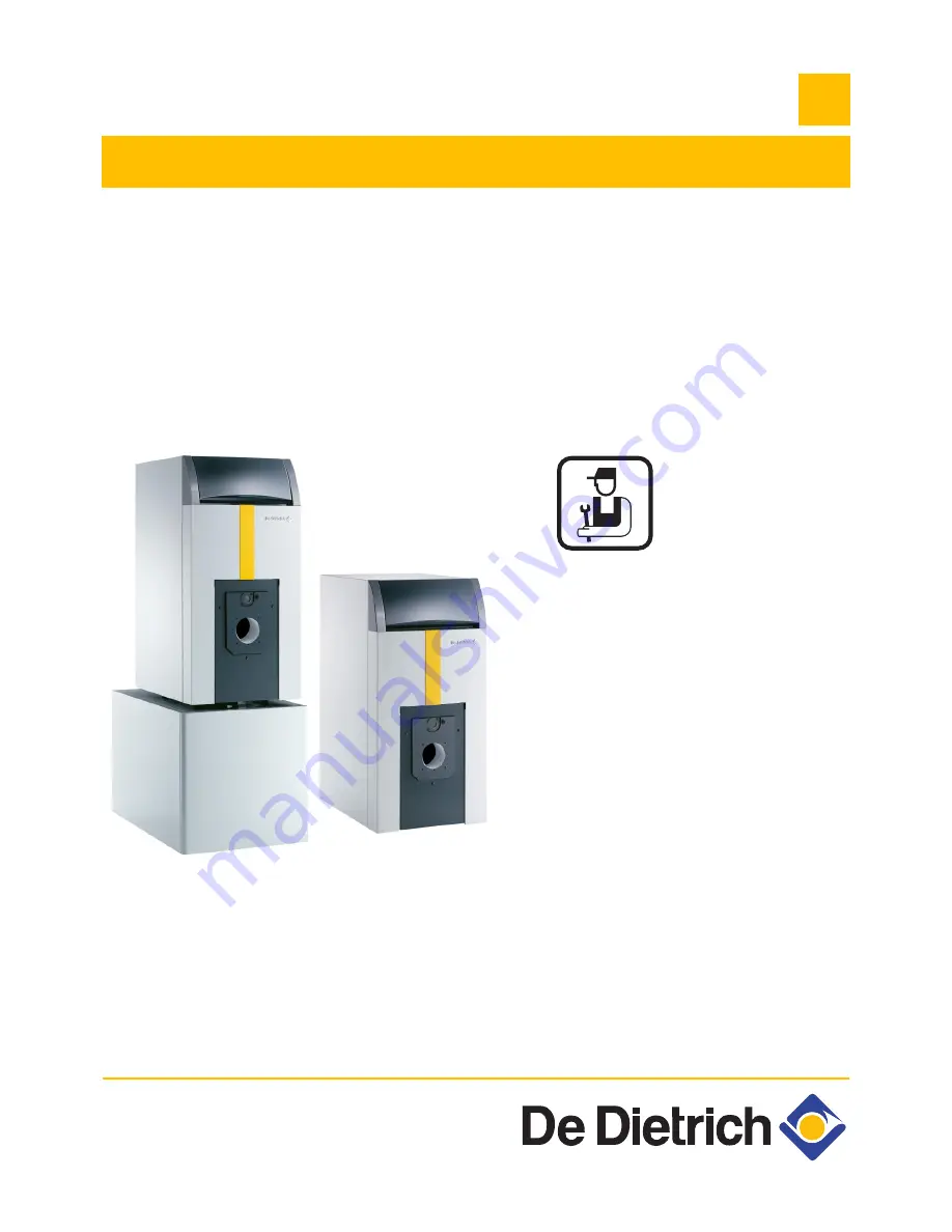
GT 220 - GT 2200
Fuel oil/gas-fired boilers
Installation and Service Manual
300008281-001-E
EN
Page 1: ...GT 220 GT 2200 Fuel oil gas fired boilers Installation and Service Manual 300008281 001 E EN ...
Page 2: ...2 GT 220 GT 2200 22 01 09 300008281 001 E Declaration of conformity CE C002209 A ...
Page 3: ...lation 11 3 1 Mounting 11 3 2 Hydraulic connections 11 3 3 Chimney connection 17 3 4 Connecting the burner 18 3 5 Electrical connections 18 3 6 Filling the installation with water 19 3 7 Commissioning 19 4 Maintenance 20 4 1 Checking and cleaning the main components 20 4 2 Boiler 20 4 3 Burner 23 4 4 Domestic hot water tank 23 5 Stopping the boiler 24 6 Spare parts GT 220 GT 2200 25 Used symbols C...
Page 4: ...afety rules applicable to combustible gas and liquefied hydrocarbon installations situated inside residential buildings and their annexes NF P 45 204 standards Gas installation formerly DTU 61 1 gas installations April 1982 addendum no 1 July 1984 Local Sanitary Regulations For appliances connected to the electricity network NF C 15 100 standards Low voltage electrical installation Rules Establish...
Page 5: ...his product may be sold in the member states of the European Union as well as in Switzerland Iceland Norway and Romania 97 23 EC Directive Gas and oil boilers with a maximum operating temperature of 110 C and hot water tanks with a maximum operating pressure of 10 bar pertain to article 3 3 of the directive and therefore cannot be CE marked to certify compliance with the directive 97 23 EC De Diet...
Page 6: ...03 2N G203 2N Number of cast iron parts 4 4 5 5 6 7 8 Nominal water flow Nominal output T 20K m3 h 2 151 2 151 2 754 2 754 3 356 3 959 4 303 Stand by losses T 30K W 197 197 213 213 226 238 247 Losses through the outer casing T 30K 64 64 68 68 70 72 73 Auxiliary electrical power Nominal output ex circulating pump W 10 10 10 10 10 10 10 Water content litres 36 36 43 43 50 57 64 Water resistance T 15...
Page 7: ...nimum average rise in temperature of 30K that the appliance can provide in the course of two successive draw offs of 10 minutes separated by a stop of 20 minutes 5 Heat exchanger inlet temperature 80 C Domestic hot water temperature 45 C 6 DHW setting 60 C Average domestic hot water temperature 40 C Boiler setting 80 C Draw off capacity Hot water flow at which water can be drawn off during a perio...
Page 8: ...20 GT 2200 Boiler and DHW calorifier connection kit A A GT 224 GT 2204 160 GT 2204 250 GT 225 GT 2205 160 GT 2205 250 GT 226 GT 227 GT 228 A 700 700 827 827 954 1081 1208 B 772 772 899 899 1026 1153 1280 Ø C 153 153 153 153 180 180 180 R1 1 4 R1 1 2 R1 1 4 R1 1 2 R1 1 2 R1 1 2 R1 1 2 E 380 380 507 507 634 761 888 ...
Page 9: ...on Ø 170 10 Drilling Ø 110 Precut Ø 130 R Thread Rp Exterior cylindrical threading sealed by flat joint 1 Adjustable feet Basic dimension 35 mm Can be adjusted from 35 mm to 50 mm 2 Adjustable feet Basic dimension 35 mm Can be adjusted from 35 mm to 40 mm 2 6 2 Installation dimensions Keep space free around the boiler to ensure good accessibility to the appliance Minimum recommended dimensions in ...
Page 10: ...hment Refer to the order of 25 06 1980 installations less than 70 kW 2 7 2 If using gas GT 220 fitted with a forced draught gas fired burner France the cross section of the aeration vent which is compulsory in the boiler room in which the boiler is installed must comply with the DTU 61 1 P 45 204 standard and in particular with the instruction on boiler room layout Book 1764 April 1982 Belgium the...
Page 11: ... and implemented to prevent heating circuit water and products contained in it returning to the drinking water system article 16 7 Departmental Health Regulations A CB disconnector area disconnector for different uncontrollable pressures must be installed for filling the heating circuit according to the NF P 43 011 standard Before making the water connections of the heating circuit and domestic ho...
Page 12: ...l sensor 23 Mixing valve outlet temperature sensor 24 DHW tank heat exchanger primary inlet 25 DHW tank heat exchanger primary outlet 26 DHW load pump 27 one way valve 28 Domestic cold water inlet 29 Pressure reducer 30 Sealed safety unit calibrated to 7 bar 31 Independent domestic hot water tanks 32 Domestic hot water loop pump optional 33 Domestic hot water temperature sensor Option 44 Thermosta...
Page 13: ...e burner Modulating burner Control panel B2 2 stages Control panel D DIEMATIC 3 PCB 2 stage burner modulating burner 3 way valve Package AD217 Panel B B2 is fitted as standard to control a second direct circuit Room temperature thermostats optional B Control panel B B2 Control panel D DIEMATIC 3 1 stage burner Control panel delivered as standard without optional equipment or 2 stage burner Modulat...
Page 14: ...er This type of installation must be controlled by the following items Control panel D DIEMATIC 3 PCB 2 stage burner modulating burner 3 way valve Package AD217 Outlet sensor after 3 way valve Package AD199 Circuit A may not be present Control panel delivered as standard 1 stage burner 1 PCB option with outlet sensor FM 48 or 2 stage burner Modulating burner PCB 2 stage burner modulating burner 3 ...
Page 15: ...is type of installation must be controlled by the following items Control panel D DIEMATIC 3 PCB 2 stage burner modulating burner 3 way valve Package AD217 Outlet sensor after 3 way valve Package AD199 2 DHW sensor options Package AD212 Control panel delivered as standard DHW sensor Package AD212 DHW sensor Package AD212 1 stage burner 1 PCB option with outlet sensor FM 48 or 2 stage burner Modula...
Page 16: ...er This type of installation must be controlled by the following items Control panel D DIEMATIC 3 PCB 2 stage burner modulating burner 3 way valve Package AD217 Outlet sensor after 3 way valve Package AD199 1 PCB mixing valve outlet sensor option Package FM48 1 DHW sensor option Package AD212 Control panel delivered as standard 1 stage burner 2 PCBs with outlet sensor FM 48 or 2 stage burner Modul...
Page 17: ...ions to be respected to ensure the draught required at the nozzle 1 Pa 0 01 mbar 1 Maximum boiler output 2 Boiler temperature 80 C Ambient temperature 20 C 3 3 2 Connection to the flue gas pipe The appliance must be installed in accordance with the Codes of Practice using a leak proof pipe made of a material capable of withstanding hot combustion gases and any acidic condensation The connection be...
Page 18: ... markings on Ø 170 3 4 2 Burner location The position of the burner head in relation to the door insulation must be respected The correct position is guaranteed with De Dietrich burners ZSee Burner instructions 3 4 3 Connection adjustment commissioning and maintenance ZSee Burner instructions 3 5 Electrical connections ZSee Control panel instructions 1 Ø 305 110 8227N013A ...
Page 19: ...nd draining valve see drawing above In this case the pipe internal Ø 14 mm must be disconnected after filling Or via the disconnector put in place by the fitter see mark 50 principle diagrams above The installation is bled of air from the top by opening one or more bleed valves Close the bleed valve s when water comes out Check that connectors are leak tight DHW tank exchanger GT 2200 For the blee...
Page 20: ...articularly the heating circuit valve 4 2 Boiler The boiler will only operate efficiently if the exchange surfaces are kept clean The boiler must be cleaned as often as necessary and like the chimney at least once a year or more in accordance with the prevailing regulations and the insurance contract taken out Cleaning operations are always done with the boiler and the electricity supply switched ...
Page 21: ... Remove the baffle plates number variable depending on the boiler model Carefully sweep the flue ways with the brush supplied for that purpose Also sweep the combustion chamber Remove soot from the bottom of the flue ways and the combustion chamber using a vacuum cleaner with a nozzle with a diameter less than 40 mm Replace the baffle plates Close the door of the combustion chamber Replace the fro...
Page 22: ... reservoir 5 l spray with separate reservoir nozzle and connecting tube The nozzles enable easy application at the back of the combustion chamber Manual pressurisation of the reservoir Motor assisted pressurisation spray with reservoir nozzle and connecting tube These sprays are intended for intensive use C Operational mode The operating mode mentioned corresponds to standard user situations Refer...
Page 23: ...lorifier instructions E Cleaning Remove the baffle plates number variable depending on the boiler model Light sweeping will remove the pulverent residues remaining after combustion The remaining pulverent residues are easy to remove by sweeping or vacuum cleaning For certain products brief application after cleaning has a preventive effect limiting deposits on the heating surfaces Replace the baff...
Page 24: ...ing If this cannot be done drain the system completely In all cases consult the fitter Domestic hot water circuit Drain the domestic water tank and pipes Precautions to take in the event of prolonged shutdown one year or more The boiler and the chimney must be swept carefully Close the door of the boiler to prevent the internal circulation of air Remove the pipe connecting the boiler to the chimne...
Page 25: ... number on the list next to the required piece must be stated when ordering replacement parts ZSee also Control panel instructions X B B2 E ER E1 E1R D D AD217 Burner instructions Domestic hot water calorifier instructions GT 2200 Boiler body 2x 2x 2x 1 1 2 10 9 11 5 8 8 33 6 1 4 2 4 3 17 7 19 17 18 28 29 29 20 21 28 29 29 22 35 31 32 11 14 13 15 16 12 11 4x 4x 2x 2x 2x 2x 2x 7 1 1 4 30 34 M000428...
Page 26: ...26 GT 220 GT 2200 22 01 09 300008281 001 E 6 Spare parts GT 220 GT 2200 Casing insulation GT 220 55 M000429B M000429B ...
Page 27: ...table foot M_10x40 30 9530 5027 Putty for nipple 31 9696 0225 nylon brush Ø 70 x 100 Length 77 mm 31 9696 0226 nylon brush Ø 70 x 100 Length 120 mm 32 8227 8502 Body screws packet 33 9602 0671 Baffle hook 34 9434 4102 Retouching spray paint anthracite grey 34 9434 4103 Retouching spray paint White 35 300014132 Distributing tube GT 228 Insulation 40 8227 5490 Complete insulating material for body 4...
Page 28: ...3 88 80 27 99 Rheiner Strasse 151 D 48282 EMSDETTEN 49 0 25 72 23 5 49 0 25 72 23 102 info dedietrich de Weggevoerdenlaan 5 B 8500 KORTRIJK 32 0 56 23 75 11 Bahnstrasse 24 CH 8603 SCHWERZENBACH 41 0 44 806 44 24 41 0 44 806 44 25 39 rue Jacques Stas L 2010 LUXEMBOURG 352 0 2 401 401 ул Крутицкий Вал д 3 109044 г Москва 7 495 988 43 04 7 495 988 43 04 dedietrich nnt ru Schemmerlstrasse 66 70 A 1110...