background image

DeCrane Aerospace Audio International

                                        LCDP-9151-201 Installation Manual  


Document # 540355, IR, 11/2007             


                Page 13 of 16 


properly.  Once  you  have  removed  the  piece  or  pieces  of  offending 

equipment,  disconnect  power  and  then  reconnect  everything  but  the 

suspect component. Reapply power and then test the functionality of the 

unit(s). 


5.2   Troubleshooting Chart 


Problem 

Possible Cause 

Solution 

Poor picture quality 

or scrambled video 

  LCD backlight 

malfunction 


  Poor video source 

  Contact DeCrane Aerospace 

Audio International 


  Change cassette 


Blank screen* 

  LCD not receiving power 


  Mother board 

malfunctioning 

  Check all cable connections 


  Contact DeCrane Aerospace 

Audio International 


* The monitor displays a black screen with the unit turned on and no video 

signal. 


6.0   Specifications 


Unit Specifications for LCDP-9151-201: 


Physical Specifications – LCDP-9151-201 


Screen Size 

15.1 (38.4 cm) diagonal 

Weight 

Approx. 5.86 lb / 2.66 kg 

Dimensions 

(l x w x h) 

See Reference Drawings 7.0 


Summary of Contents for LCDP-9151-201

Page 1: ...7300 Industry Drive North Little Rock AR 72117 Phone 501 955 2929 Fax 501 955 2988 www decraneaerospace com Installation Manual LCDP 9151 201 15 1 LCD Monitor with Plug In Arm Document 540355 ...

Page 2: ... Subject Manual Revision Revision Date Table of Illustrations Section Description Page 2 3 Typical Application 4 2 6 Plug In Arm Mobility 5 6 7 0 Reference Drawings 14 16 PROPRIETARY NOTICE Despite any other copyright notice this document and information disclosed herein contains confidential proprietary designs owned by DeCrane Aerospace Audio International Neither this document nor the data cont...

Page 3: ...lity 5 3 0 Installation 7 3 1 Preparation 7 3 2 Unpacking and Inspection 7 3 3 Cautions Warnings 8 3 4 Wiring Requirements 8 3 5 Electrical Characteristics 10 3 6 Mating Connector Information 11 3 7 Pinout Assignment Descriptions 11 4 0 Instructions for Continued Airworthiness 11 4 1 Airworthiness Limitations 11 4 2 Cleaning Method 11 5 0 Troubleshooting 12 5 1 General Troubleshooting Procedures 1...

Page 4: ...ve matrix drive system provides brilliant and accurate color reproduction excellent high contrast images cross talk suppression and fast response time with no distortion or smearing 1 3 Optional Equipment DeCrane Aerospace Audio International offers a comprehensive family of Cabin Control Modules and Source Equipment such as DVD Players and Videocassette Players These modules provide convenient so...

Page 5: ...ightness and color hue for video 2 2 Communication This unit incorporates an RS 485 serial data bus interface for communication purposes to other network connected devices All RS 485 serial data bus electronic interface parameters are compliant to DeCrane Aerospace Audio International document 640071 2 3 Typical Application 2 4 Typical Interfaces 2 4 1 Typical Video Input Analog interfaces include...

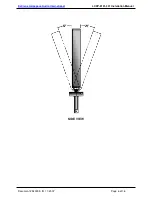
Page 6: ...teeing a reduction in interference to ensure a high quality display 2 5 3 Inside the monitor a cooling fan ventilates internal components and prevents undesirable heat buildup The fan is thermostatically controlled and only runs when heat build up requires it to providing a much quieter viewing experience than many monitors 2 6 Plug In Arm Mobility The Plug In Arm affords the LCDP 9151 201 a wide ...

Page 7: ...DeCrane Aerospace Audio International LCDP 9151 201 Installation Manual Document 540355 IR 11 2007 Page 6 of 16 SIDE VIEW ...

Page 8: ...ose to the source equipment as possible in order to reduce the possibility of noise introduced into the video Refer to Section 6 0 for unit dimensions 3 2 Unpacking and Inspection 3 2 1 Carefully open the packaging and remove the LCDP 9151 201 Verify that all components have been included in the package per the packing list Inspect the unit for damage Retain the packing materials and packing list ...

Page 9: ...rnal cables should be carefully studied and planned before attempting installation of the equipment Allow adequate space for installation of cable and connectors Avoid sharp bends and placing cables near aircraft control cables Maintain a minimum clearance of three 3 inches from any control cable If wiring is run parallel to combustible fluid or oxygen lines maintain a separation of six 6 inches b...

Page 10: ...le shields shall be grounded at the source Use of individual wires rather than proper coaxial cable connections through production breaks is unacceptable and will cause significant and detrimental noise introduction to the video signal supplied to the LCDP 9151 201 Serial digital video connections are recommended to use shielded coaxial cable in accordance with PIC V76261 or equivalent SD SDI vide...

Page 11: ...d XGA PC Graphics Operating Temperature 32 to 122 F 0 to 50 C Storage Temperature 4 to 158 F 20 to 70 C Composite Video Input 1 V p p 75 Component RGB Input Industry Standard Digital Video Input ANSI SMPTE 259M 1997 3 5 2 The LCDP 9151 201 utilizes a 11 pin connector that provides power input ground video input monitor on off control and RS 485 Two 2 pins are also provided These ID pins allow for ...

Page 12: ...riptions P1 Pin Description 1 28 VDC Power Input 2 Ground 3 Composite Video In 4 Composite Video In 5 Databus A 6 Databus B 7 Shield 8 ID0 9 ID1 10 In Common A1 Video Input SDI 4 0 Instructions for Continued Airworthiness 4 1 Airworthiness Limitations No periodic scheduled maintenance or calibration is required for continued airworthiness of the LCDP 9151 201 If the unit fails to perform to specif...

Page 13: ...5 0 Troubleshooting 5 1 General Troubleshooting Procedures Verify power to the unit by rechecking 28 VDC power is applied to the proper pins on the unit Use a voltmeter to verify correct level Remove power from the unit for at least one 1 minute and reapply power Recheck all connections to the unit for security Check all harness runs for possible pinching Recheck all pinouts for application accura...

Page 14: ...ion Poor picture quality or scrambled video LCD backlight malfunction Poor video source Contact DeCrane Aerospace Audio International Change cassette Blank screen LCD not receiving power Mother board malfunctioning Check all cable connections Contact DeCrane Aerospace Audio International The monitor displays a black screen with the unit turned on and no video signal 6 0 Specifications Unit Specifi...

Page 15: ...7 Page 14 of 16 7 0 Reference Drawings 7 1 Dimensions and Connections LCDP 9151 201 The following diagrams show the unit dimensions mounting locations and connector locations for the LCDP 9151 201 All dimensions are given with tolerance of 0 03 0 08 cm 7 2 Dimensions and Connections BSE 9101 201 x ...

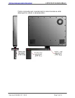
Page 16: ...allation Manual Document 540355 IR 11 2007 Page 15 of 16 BSE 9101 201 x Plug In Monitor Base is required for mounting This base is sold separately Contact your DeCrane Aerospace Audio International representative for details 7 3 Friction Joints LCDP 9151 201 ...

Page 17: ...erospace Audio International LCDP 9151 201 Installation Manual Document 540355 IR 11 2007 Page 16 of 16 Friction Joints allow arm movement with minimum resistance while allowing arm to remain in desired position ...

Reviews: