background image

Prior to construction, check with your local regulatory agency  
for special code requirements in your area.


Start with an Inside Corner piece when applicable.

Guidelines: 

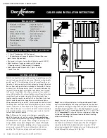
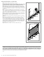
•  The height of the secondary handrail must be installed between      
  34” and 38” above the surface, regardless of the height of the guard. 
•  We recommend that handrails be dry fit prior to final installation to  
  eliminate cutting and fastening errors. 
•  IMPORTANT: The secondary handrail must be attached to a structural  
  support. When installing mounting brackets on post sleeves, ensure  
  the hardware attaches to the structural support. 
•  For maximum strength, brackets should be used at every post and  
  every joint, or as closely as possible to the joint. 
•  An adhesive may be applied to further reinforce construction.


•  Handrails must be supported every 6’ on-center  
  by a mounting bracket.

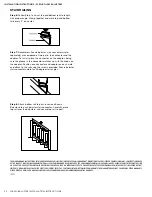
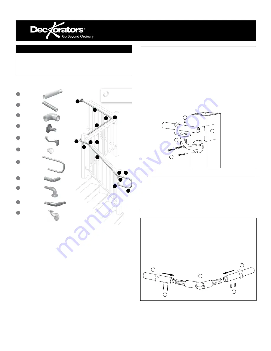
Handrail with Aluminum Insert

Step 1: 

Dry fit handrails to determine proper lengths prior to  

cutting rails. 

Step 2: 

Measure and cut rails to proper lengths for all runs. 

Step 3: 

Install to handrail component, following instructions for the 

components.

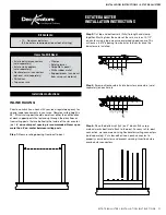
Items You Will Need

•  Drill
•  Chop/Miter Saw
•  Quick Clamps
•  PVC Cleaner

•  Pencil
•  Tape Measure
•  Level
•  #2 Square Drive Bit

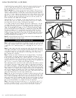
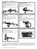
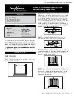
Aluminum Offset Bracket (Line Post Mounting Bracket)

Step 1:

 Measure 2-1/2” less than the handrail height to determine 

bracket position. Mark surface.

Step 2:

 Align the top of the bracket mounting plate with the mark 

made in Step 1. Drill 5/32” pilot holes and attach to the desired 
surface using the 2-1/4” screws provided.

Step 3:

 Clamp handrail to bracket at appropriate location to 

secure in place.

Step 4:

 Drill 5/32” pilot holes and attach handrail using the 1” 

screws provided.

3

4

1

2

2-1/2"

AluminumBracket.ai

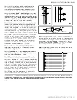
External Swivel

Step 1:

 Adjust external swivel to desired angle and install set 

screw.

Step 2

: Cut handrail with aluminum insert to desired length.

Step 3:

 Insert external swivel bracket into the aluminum portion of 

the handrail.

Step 4:

 Pre-drill handrail and bracket with 5/32” drill bit and install 

1” screw provided.

1

2

4

ExternalSwivel.ai

4

3

End Caps optional

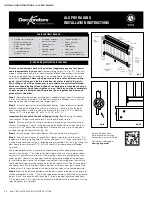
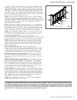
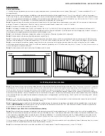
Typical ADA Railing Installation

Components

:

ADA Secondary 

Handrail 104"

6" Straight Joiner

4" Inside/Outside 

Corner

Straight End Wall 

Bracket

Inside Corner Bracket

End Cap

P-Loop Return

6" Adjustable Joiner

90° Quick Return 

Bracket

External Swivel

Offset Bracket

1

1

1

1

2

3

3

3

4

4

5

5

6

7

7

8

8

9

9

10

10

11

11

11

or

8


or


10


Optional Beauty Ring 

Joint Cover

(Use As Necessary)

ADAinstall314_ADA  4/4/14  9:59 AM  Page 2

ADA Compliant Handrail Guidelines and Installation

SECONDARY HANDRAIL INSTALLATION INSTRUCTIONS    47

INSTALLATION INSTRUCTIONS • SECONDARY HANDRAIL

Summary of Contents for ALX CLASSIC

Page 1: ...on product offerings how to buy guides installations and warranties 2014 Pro Guide RAILING BALUSTERS POST CAPS LIGHTING ACCESSORIES 2020 TECHNICAL GUIDE DECKING RAILING BALUSTERS ACCESSORIES POST CAPS LIGHTING LATTICE PORCH TECH GUIDE ...

Page 2: ...newest on trend styles from the brand always leading design innovation Deckorators offers the quality and selection to transform decks into a reflection of each homeowner The first name in outdoor decorating we ve staked our reputation on your satisfaction In fact we re so confident we stand firmly behind that reputation with some of the best first of their kind product warranties in the industry ...

Page 3: ...STAIR RAIL SECTION HARDWARE INCLUDED 6 Rectangle ALX Contemporary Preassembled Stair Rail 36 or 42 Available colors Textured Black Textured White Weathered Brown Textured Bronze and Brushed Titanium 8 Rectangle ALX Contemporary Preassembled Stair Rail 36 or 42 STEP 4 CHOOSE YOUR STAIR POSTS 2 5 x 2 5 ALUMINUM POST KITS PURCHASE 1 POST KIT PER STAIR RAILING PLUS 1 TO END EACH RUN TRIM AND POST CAP ...

Page 4: ...tured Bronze 8 Rectangle ALX Contemporary Cable Stair Rail 46 stair spacers included for 36 and 42 stair heights Trim to fit STEP 4 CHOOSE YOUR STAIR POSTS 2 5 x 2 5 ALUMINUM POST KITS PURCHASE 1 MIDDLE STAIR POST KIT FOR IN BETWEEN TWO STAIR RAILING SECTIONS PLUS 1 BOTTOM STAIR POST TO END THE CABLE RUN AT THE BOTTOM TRIM AND POST CAP INCLUDED 49 Cable Stair Middle Post Kit with Leveling Plate fo...

Page 5: ... 1 4 Baroque for 36 line rail 5 pack screws included Available colors Black White and Bronze 40 Baroque for 42 line rail 5 pack screws included 32 1 4 Arc for 36 line rail 5 pack screws included Available colors Black and Bronze TRADITIONAL ALUMINUM BALUSTERS PURCHASE 1 5 10 PACKS PER 6 RAIL OR 2 10 PACKS PER 8 RAIL 32 Traditional for 36 line rail 10 pack screws included Available colors Black and...

Page 6: ... 26 Clear Scenic Glass for 36 5 pack 32 Clear Scenic Glass for 42 5 pack screws included STEP 3 SELECT YOUR CORRESPONDING BALUSTER CONNECTORS ALUMINUM BALUSTER CONNECTORS PURCHASE 1 20 PACK PER 1 BALUSTER PACK ADD STAIR ADAPTORS AS NEEDED Baluster Connectors 20 pack use with Classic Balusters Available colors Black and White Stair Connectors 20 pack use with Classic Balusters Available colors Blac...

Page 7: ...eight or 12 packs for a 42 rail height required for each start or stop of a run post STEP 3 CABLE Available in 100 and 500 lengths STEP 4 SUPPORT One spacer required for a 6 section two spacers required for an 8 section STEP 5 POST PROTECTORS Post protectors are required for turning 45 degree corners sold in packs of 10 STEP 6 ADD YOUR ALX PRO POST SLEEVE KITS if applicable STEP 7 CHOOSE YOUR POST...

Page 8: ...t Classic Round Balusters for 36 or 42 Rail Height Available colors Satin Black Matte Black Textured White Weathered Brown 6 Stair Rail Kit Estate Square Balusters for 36 or 42 Rail Height 8 Stair Rail Kit Classic Round Balusters for 36 or 42 Rail Height 8 Stair Rail Kit Estate Square Balusters for 36 or 42 Rail Height STEP 4 CHOOSE YOUR STAIR POST KITS 2 5 x 2 5 ALUMINUM POST KITS PURCHASE 1 POST...

Page 9: ... cuidado y limpieza Deckorators es una marca comercial de Universal Consumer Products Inc en los EE UU La garantía está disponible en www deckorators com Guarde las etiquetas UPC como comprobante de compra Rangement Gardez couvert avant l installation Installation Toutes les planches doivent être espacées correctement pour permettre la dilatation et le retrait Consultez les directives d installati...

Page 10: ...he deck boards starting from the outside edge of the platform and work toward anchor wall so that ripped pieces abut the wall Start installing from one end of the board and work toward the other end of the board OR Start installing from the center of the board and work out toward the ends of the board Do not install by fastening each end first and working toward the middle Continue installing deck...

Page 11: ...g a product be certain to read Stringer Stair tread Eotek2 pdf 9 max 36 min 5 stringers required 11 min depth 1 8 min gap THE DIAGRAMS AND INSTRUCTIONS IN THIS BROCHURE ARE FOR ILLUSTRATION PURPOSES ONLY AND ARE NOT MEANT TO REPLACE A LICENSED PROFESSIONAL ANY CONSTRUCTION OR USE OF THE PRODUCT MUST BE IN ACCORDANCE WITH ALL LOCAL ZONING AND OR BUILDING CODES THE CONSUMER ASSUMES ALL RISKS AND LIA...

Page 12: ...nd care and cleaning information Deckorators is a trademark of Universal Consumer Products Inc in the U S Warranty available at www deckorators com Save UPC end tags for proof of purchase 7928 11 14 2014 2015 Universal Forest Products Inc All rights reserved 1801 E Lessard Prairie du Chien WI 53821 877 463 8379 Chaque planche de platelage possède une apparence unique et devrait donc être disposée ...

Page 13: ...zzle should be used only to lightly wet or rinse wood or composite deck surfaces There are many deck wash and exterior cleaning products available at retail It is important to make sure you use a cleaner specifically intended for your application After selecting a product be certain to read understand and follow all instructions supplied by the manufacturer Some cleaning products and inhibitors ma...

Page 14: ...ions Residential parquet patterns and diago nal or herringbone designs require joist spacing of 12 on center Contact Deckorators product support at 800 332 5724 for commercial appli cations Use 1 4 for side gapping fig 1 Warmest annual temperature F expected in region F 20 30 40 50 60 70 80 90 100 110 120 20 1 8 1 8 1 8 1 8 1 8 3 16 3 16 1 4 1 4 5 16 5 16 30 1 8 1 8 1 8 1 8 1 8 3 16 3 16 1 4 1 4 5...

Page 15: ...dden fastener into the groove and cen ter on the joist fig 3 Install the preset screw at a 90 angle through the Stowaway fastener and drive flush Do not over tighten The fastener wings must remain level with the joist for the next board to fit correctly fig 4 Step 4 Install one Stowaway fastener at each joist location Slide the next board into place so the wings on the previous fasteners fit into ...

Page 16: ...diate A pressure washer with a fan tipped nozzle should be used only to lightly wet or rinse wood or composite deck surfaces There are many deck wash and exterior cleaning products available at retail stores It is important to make sure you use a cleaner specifically Note To predrill a groove on one side of deck board we recommend using a 5 32 T slot cutter Step 7 Install one Stowaway fastener at ...

Page 17: ...t the cleaner in a small inconspicuous area prior to applying it to the entire deck Tips for snow removal Care should be taken when removing snow from your deck to avoid damaging the deck surface Use a plastic snow shovel one without a metal edge A stiff push broom can work very well and minimizes lifting Light snow can be cleared using a leaf blower Do not attempt to break up or scrape ice from t...

Page 18: ...into the substructure design Deckorators porch flooring is not intended to be used in applications that require a watertight surface Caulk and adhesives should not be used in the tongue and groove Painting is not recommended Standard Picture Frame Diagonal 45 16 16 12 Gapping Requirements Above 32 F 0 C Below 32 F 0 C End to End 1 8 3 16 End to Side 1 8 3 16 Abutting Solid Objects 1 8 1 4 Cutting ...

Page 19: ...s is due to naturally occuring variations in polymers Purchasing all required porch flooring material at one time is recommended as manufacturing runs can produce slightly different colors Do not install if color variation is not acceptable Mold and mildew can be a nuisance on any exterior building surface regardless of the material If the conditions are right they will grow on wood plastic concre...

Page 20: ...s stair tread surface Do not over tighten Use two fasteners per stair tread at each stringer For any stair tread where two boards meet end to end an additional stringer is required so each end is supported Figure 2 Always pre drill a pilot hole and countersink at board ends when using other composite or wood screws Be careful not to over tighten screws near board ends Stringers spacing is a maximu...

Page 21: ...y be necessary to try more than one product For ongoing preventive maintenance follow the manu facturer s recommendation Note Deckorators is not suitable for structural use It should not be used for primary load bearing members such as posts joists beams or stringers The same common sense precautions should be taken when handling Deckorators as with wood or other building materials Dust masks and ...

Page 22: ...TION INSTRUCTIONS Tools and Items Needed Drill power screwdriver 1 8 drill bit Circular saw with carbide tip blade 2 composite wood deck screws Tape measure Carpenter s pencil Safety glasses goggles Notice to installers DO NOT use cordless impact drivers Set drill speed to 1500 1750 RPM Max torque not to exceed 23 inch pounds Pre drill knots or dense hardwood THE DIAGRAMS AND INSTRUCTIONS IN THIS ...

Page 23: ... be fully supported along the underside They are intended to create a floating deck surface on top of an appropriate structure such as a flat membrane roof or concrete slab Care must be taken during construction to avoid damaging the roof s surface A roof top deck is a unique application Consult with a licensed contractor to ensure your roof is a good candidate for a roof top deck The roof must ha...

Page 24: ...cluding the decking 5 4 or 1 1 2 deck boards do not provide sufficient material for a safe installation If necessary add additional material to the underside of the surface fig 2 Step 2 Position the post assembly onto the location where it will attach to the deck Four 3 8 diameter mounting holes are provided on the base When the final position is determined mark the base hole locations Remove the ...

Page 25: ...pports to the support block connectors Mark the location of the rail support on the deck surface and attach the other rail support connector to the deck using the included screw fig 7 For Anodized Brushed Titanium Railing drill two drain holes through the bottom of the rail to prevent trapping water Center drain holes between two baluster locations as baluster can block the pathway and stop water ...

Page 26: ...stance between the post and the first baluster should be less than 4 and equal on both ends Once the railing is in position clamp the railing to the posts Step 5 Temporarily assemble the swivel brackets Position the swivel bracket in location and mark the rail and post Repeat for other end of railing Note The distance from the end of the top rail to the first stair baluster will be 1 1 16 longer t...

Page 27: ... attached threaded stud on one end plastic spacer SS washer brass locknut and cap 1 Pull lock fitting with Delrin washer and cap Available in lengths of 5 10 15 20 25 30 40 or 50 In Line Railing Installation Instructions Prior to construction Check with your local regulatory agency for special code requirements in your area Common railing height is 36 or 42 Pre drill all screw holes for best resul...

Page 28: ...s plumb Fully tighten the post fasteners to secure the base to the deck structure Note Recommended 5 16 x 4 or longer lag screws fig 6 Step 5 Finish by sliding a post base trim optional over each post for a finished look Step 6 Measure the distance between installed posts to determine the length of the top rail The rails are sized for 6 and 8 on center posts when using 2 5 posts and include space ...

Page 29: ...bly with the leveling plate inserted between the deck and the post base and aligned with the predrilled holes Insert the post fasteners NOT INCLUDED and partially tighten Using a level adjust the leveling set screws with a 3 16 allen wrench until the post is plumb Fully tighten the post fasteners to secure the base to the deck structure Note Recommended 5 16 x 4 or longer lag screws Step 4 Finish ...

Page 30: ... dia 7 32 dia 7 32 dia 7 32 dia Hole size for Intermediate Posts for 1 8 dia cable passing cable only Hole size for Intermediate Posts for 3 16 dia cable passing cable only For Intermediate Post passing cable through CS Tube side wood post only For End Post using Pull Lock fitting For End Post using Threaded Stud 5 32 Drill Bit 1 4 Drill Bit 29 64 Drill Bit 1 8 Hex Wrench Cut off Tool Used to cut ...

Page 31: ...e fitting NOT what you want C Feed Cable through Intermediate Posts 1 Feed the bare end of the cable through all intermediate posts cable braces and through the end post where you will be installing the Pull Lock fitting D Feed Crimp Cable through Corner Posts Instructions for going through corners for both wood and metal posts are available at our website Scan the QR Code at right with your smart...

Page 32: ...able give it a sharp pull downward mid span to help set the wedges then re tension as necessary in the same sequence Be aware that the cable may move as much as 3 16 toward the tensioning terminal as the wedges seat G Trim Excess Cable 1 When all of the cables are tight cut off any exposed thread as near to the locknut as possible by using a cut off wheel or hack saw 2 Twist the cap over the lockn...

Page 33: ...ze for 1 8 or 3 16 dia cable installation 5 32 dia for 1 8 dia cable 7 32 dia for 3 16 dia cable 5 32 dia for 1 8 dia cable 7 32 dia for 3 16 dia cable End Post using Threaded Stud End Post using Pull Lock End Post using Threaded Stud End Post using Pull Lock 29 64 dia 1 minimum 29 64 dia 9 32 dia 1 4 dia 1 4 dia for CS Tube Minimum 1 9 Metal Post Minimum 4 x 4 Wood Post 29 64 dia 2 minimum for CS...

Page 34: ...hrough Intermediate Posts 1 Pass bare end of cable through intermediate post s and through other end post which includes post protector tube if wood post D Feed Crimp Cable through Corner Posts As this section deals with passing cables through corners which you will not be doing with stairs please proceed to Section E Washer Brass Locknut Stud Bushing Feed bare end of cable through all other posts...

Page 35: ...ou push it onto the cable If the cable begins to unravel you are rotating the fitting in the wrong direction Press to hold fitting against post Pull cable tight Pull cable tight Push the cable through the fitting Rotate the fitting clockwise Washer Push the cable through the post Mark cable Note If you have trouble inserting the cable into the fitting it may be because the locking wedges have beco...

Page 36: ...le may move as much as 3 16 toward the tensioning terminal as the wedges seat 3 At both ends of the run you are going to create a sharp bend in the cable where it exits the post post protector tube in the wood post by placing a block of wood for protection of the post on the cable next to the post tube at the face of each post and striking it with a hammer If tension has diminished slightly as a r...

Page 37: ...ck fitting 3 Return to the swageless terminal Cut the cable flush with the hole in the back of the fitting using a cut off wheel Cut off Twist cap onto lip Twist cap over locknut G Trim Excess Cable 1 When all of the cables are tight cut off any exposed thread as near to the locknut as possible by using a cut off wheel or hack saw 2 Twist the cap over the locknut Cut off Cut off ...

Page 38: ...ould be a minimum of 1 1 2 longer than the overall railing height Allow an additional 1 1 2 in your calculation if in stalling the optional cap rail fig 3 following page Example For a 36 high railing trim post sleeve to a minimum of 37 1 2 39 with cap rail Post sleeve can be left longer if desired Some wood preservatives may cause an undesirable reaction when placed in direct contact with aluminum...

Page 39: ...s fig 5 Step 8 Position the bottom rail between posts and center Note Check building code requirements for maximum spacing between deck surface and bottom of rail sweep Spacing of 3 is recommended but can be more or less if codes allow fig 3 Mark the location of the bracket on both posts Remove rail Mark the screw locations and pre drill through the post sleeve only using a 1 4 drill bit Attach ea...

Page 40: ... interior face of the stair stringer Plumb again The 4x4 railing post should be bolted to the inside of the stair stringer using two 1 2 x 6 galvanized carriage bolts Corner posts use a third carriage bolt inserted through the adjacent joist refer to figure 2b Ground level posts should be set in concrete Step 3 Complete stair tread installation prior to installing post sleeves Trim 4x4 post sleeve...

Page 41: ...o the stair connectors while working from one end of the railing to the other Tap with a rubber mallet if needed to eliminate any gaps Attach the rail to each bracket by pre drilling with 1 8 drill bit and using four 1 screws Tip Use a driver extension bit to avoid marring the rail or post sleeve with the drill chuck Traditional Baroque Arc and Glass balusters Place the top rail in position Attach...

Page 42: ...et to protect the fittings from raw steel Avoid installing with rusty tools as they leave rust deposits on the surface of the fittings almost immedi ately After installation it is critical to clean the system completely with a stainless cleaner and a soft clean rag in order to clear the surface from carbon deposits Step 1 Determine the number of railing posts needed for your deck Post spacing is 6...

Page 43: ...l the top rail to your post Use the included connectors to assemble the cable spacer s to the top rail Line up the connector with the center of your rail for 6 applications and mark for positioning Position cable spacer on deck and fasten with included screws Note Use one cable spacer per 6 section and two per 8 section 1 spacer every 2 5 ft for 8 Step 8 Install eye lag screws into the predrilled ...

Page 44: ...e deck Four 11 32 diameter mounting holes are provided on the base When the final position is determined mark the base hole locations Remove the post assembly and drill 15 64 holes in the marked locations into the deck and reinforcement Step 3 Reposition the post assembly with the leveling plate inserted between the deck and the post base and aligned with the predrilled holes Insert the post faste...

Page 45: ...ep 1 Begin by determining where the top and bottom post will be located Mark the desired location of the post Note To ensure post location is compatible with railing prior to securing to the deck place both posts in position and lay the bottom rail along the stair nosing from top to bottom adjacent to both posts On the rail side of the post measure up from the top of the rail and ensure there is a...

Page 46: ... a bracket to the post with two 1 3 4 screws at one end Repeat for the other end Lower the top rail into position placing the balusters onto the stair connectors while working from one end of the railing to the other Tap with a rubber mallet if needed to eliminate any gaps Attach the rail to each bracket by predrilling with a 1 8 drill bit and using two 3 4 screws Tip Use a driver extension bit to...

Page 47: ...um Offset Bracket Line Post Mounting Bracket Step 1 Measure 2 1 2 less than the handrail height to determine bracket position Mark surface Step 2 Align the top of the bracket mounting plate with the mark made in Step 1 Drill 5 32 pilot holes and attach to the desired surface using the 2 1 4 screws provided Step 3 Clamp handrail to bracket at appropriate location to secure in place Step 4 Drill 5 3...

Page 48: ...ion purposes only and are not meant to replace a licensed professional Any construction or use of the product must be in accordance with all local zoning and or building codes The consumer assumes all risks and liability associated with the construction or use of this product The consumer or contractor should take all necessary steps to ensure the safety of everyone involved in the project includi...

Page 49: ...mplete The caulk should be on the outside of the connector where the baluster will make contact with the connector s outer edge Note Specific types of treated lumber are known to corrode aluminum Deckorators baluster connectors provide a barrier between the aluminum balusters and treated lumber to ensure long term performance Deckorators baluster connectors sold separately Deckorators stair connec...

Page 50: ... Step 6 For rail sections longer than 4 support blocks are recommended These can be made from leftover 2x4 rail material Properly position the support block and toe nail it to the bottom rail and deck board Step 7 Stair rails and balusters can present an installation challenge Deckorators angled stair rail connectors sold separately create a snug and accurate baluster fit for stair angles at 35 de...

Page 51: ...arting from the center of the rails mark out 4 1 2 on center using a tape measure or marked speed square This will leave a 3 3 4 opening from baluster to baluster once the balusters are installed Step 3 Screw on Deckorators Estate baluster connectors sold separately on each mark Estate baluster connectors sold separately Estate stair adaptors sold separately Deckorators rail connectors optional so...

Page 52: ...E ANY OTHER WARRANTY EITHER EXPRESS OR IMPLIED AND SHALL NOT BE LIABLE FOR ANY DAMAGES INCLUDING CONSEQUENTIAL DAMAGES STAIR RAILING Stairs Follow Step 1 and cut 2x4s to length with proper angle With 2x4s laying flat start from the center of the rails and mark every 5 1 2 on center Screw on Deckorators Estate baluster connectors with stair adaptors sold separately to complete your stair rail The a...

Page 53: ...ded Never span more than 8 on center between railing posts Step 1 Attach top and bottom rails to posts according to local building codes The distance from the deck surface to the top of the rail is typically 36 Use a baluster as a guide to determine placement of the bottom rail Find the center of the top and bottom rails and mark Rail length 2 center of rail Installation Instructions Step 2 The ba...

Page 54: ...Y EITHER EXPRESS OR IMPLIED AND SHALL NOT BE LIABLE FOR ANY DAMAGES INCLUDING CONSEQUENTIAL DAMAGES STAIR RAILING Step 1 Attach top and bottom stair rails to posts according to local building codes The distance from the stair tread to the top of the rail is typically 36 Use a baluster as a guide to determine placement of the bottom rail Find the center of the top and bottom rails and mark Rail len...

Page 55: ...urface to the top of the rail is typically 36 Use a baluster as a guide to determine placement of the bottom rail Find the center of the top and bottom rails and mark Rail length 2 center of rail Installation Instructions Step 2 Attach the first baluster on center of the center line using four of the screws provided Drive each screw until the rubber grommet begins to mushroom Do not over tighten S...

Page 56: ...EARING THE APPROPRIATE SAFETY EQUIPMENT EXCEPT AS CONTAINED IN THE WRITTEN LIMITED WARRANTY THE WARRANTOR DOES NOT PROVIDE ANY OTHER WARRANTY EITHER EXPRESS OR IMPLIED AND SHALL NOT BE LIABLE FOR ANY DAMAGES INCLUDING CONSEQUENTIAL DAMAGES STAIR RAILING Step 1 Attach top and bottom stair rails to posts according to local building codes The distance from the front edge of the stair tread to the top...

Page 57: ... side of center with all balusters 6 1 2 on center Mark both rails 6 1 2 on center starting from the desired location Step 3 Screw on one Deckorators Scenic baluster connector sold separately on each mark using the screws provided 5 Glass balusters 20 Stainless steel screws You will need 1 5 balusters per linear foot of handrail Prior to construction check with your local regulatory agency for spe...

Page 58: ...N LIMITED WARRANTY THE WARRANTOR DOES NOT PROVIDE ANY OTHER WARRANTY EITHER EXPRESS OR IMPLIED AND SHALL NOT BE LIABLE FOR ANY DAMAGES INCLUDING CONSEQUENTIAL DAMAGES STAIR RAILING Step 6 Follow Step 1 and cut top and bottom rails to length with proper angle Clamp together and mark top and bottom rails every 9 on center Step 7 Deckorators Scenic baluster stair connectors sold separately are compos...

Page 59: ...the battery compartment to allow connection to the termi nal Ensure battery is firmly in place remove switch is in on position there is no on off switch Step 3 Replace the solar panel Step 4 Your solar post cap light is now ready to be attached to your post Figure 1 Solar Panel Figure 1 Figure 2 Figure 3 Concealed Solar Post Caps Step 1 Access the inside of the solar light by grasping the top of t...

Page 60: ...llation We recommend reapplying the finish annually to preserve the wood s natural beauty and protect it from the elements 9710_12 17 Deck and Dock Solar Lights Step 1 Remove the exterior bottom cover using a regular screwdriver and remove the plastic tab to allow battery connection to the terminal Step 2 Reinstall the exterior bottom cover and tighten securely Step 3 Drill a 1 3 8 35mm hole in th...

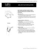
Page 61: ...CIÓN SI NU CONSULTE A UN ELECTRICISTA CA PARA REQUISITOS DEL CÓDIGO Notas de operación 1 Esta luminaria está diseñada para se aprobados por sistemas de CA de 1 9 15 voltios 2 Gama completa atenuada mediante tipo MLV del lado de 120 VCA del tr atenuador PWM puede usarse en el CC Instrucciones d Spanish Installation Instructions Family Luna Post Cap Item No D58820 D58840 English Luminaire Mounting P...

Page 62: ...ed to the mounting surface attach the cover plate CP by angling the plate at 45 degrees until the underside lip of the cover plate hooks onto the cover bracket and tighten screw to fix the cover plate in place NOTE Make sure the cut corner hole on the cover plate is in the bottom half of the fixture Family Luna Step Item No D15508 Famille Luna 2018 Universal Forest Products Inc 68956 U S Hwy 131 W...

Page 63: ...STALLATION CONTINUED Luna Step Light Installation Without A Box Cut Out Template Cut 1 5 8 Deep Cut Out Area LUNA STEP LIGHT INSTALLATION INSTRUCTIONS 63 INSTALLATION INSTRUCTIONS DECKORATORS BY HINKLEY LUNA STEP LIGHTS ...

Page 64: ...leads from the luminaire and connect to the main supply wire using the wirenuts Fill wirenuts with appropriate silicone to waterproof consult wiring instructions from the transformer or power supply Operation Notes 1 This luminaire is designed to be operated with Deckorators approved 12 Volt AC systems or other 9 15 Volt DC systems 2 Full range dim by using MLV type dimmer control of the 120 VAC s...

Page 65: ...on output side of DC systems ADVERTENCIA DE SEGURID DURANTE LA INSTALACIÓN CONSULTE A UN ELECTRICIS PARA REQUISITOS DEL CÓD Notas de operación 1 Esta luminaria está diseñada p aprobados por sistemas de CA 9 15 voltios 2 Gama completa atenuada me tipo MLV del lado de 120 VCA atenuador PWM puede usars CC Instruccion Spanish Installation Instructions Family Deck Sconce Item No D1549 English Luminaire...

Page 66: ...ding practices 3 Strip the two wire leads from the luminaire and connect to the main supply wire using the wirenuts Fill wirenuts with appropiate silicone to waterproof Consult wiring instructions from the transformer or power supply Cableado de la Luminaria 1 Para evitar descargas eléctri suministro eléctrico antes d 2 Pase el cable hasta la parte i prácticas de construcción lo 3 Pele los dos cab...

Page 67: ...ostcover and 52 above the deck for a proper fit with the 53 postcover B Posts should be installed on the inside of the deck frame to allow the postcover to rest entirely on the decking Step 2 Install postcover C A 6x6 S4S smooth four sides wood post can vary from 5 1 4 to 5 5 8 in thickness and may be subject to slight irregularities Use wood shims at the top and bottom of the post to ensure a snu...

Page 68: ...within the location of the connector bracket using 100 grit coarse aluminum oxide sandpaper Step 6 Finish the job K To complete the first rail section installation drill holes and install connectors on the other side L Cut rails to fit and place them as you go Secure rails to connectors with the screws provided Finish deck railing M If using postcover post caps use a strong exterior masonry adhesi...

Page 69: ... and excess adhesive from the outside of the post cover Hold the two sides together using two padded clamps or adjustable straps for the time recommended on the concret adhesive If installing a two piece post cap on top of the bottom post cover and around a post Choose the appropriate post cap for the size of your post nominal 4x4 or 6x6 Apply a bead of concrete adhesive to the top edge of the low...

Page 70: ...E DIAGRAMS AND INSTRUCTIONS IN THIS BROCHURE ARE FOR ILLUSTRATION PURPOSES ONLY AND ARE NOT MEANT TO REPLACE A LICENSED PROFESSIONAL ANY CONSTRUCTION OR USE OF THE PRODUCT MUST BE IN ACCORDANCE WITH ALL LOCAL ZONING AND OR BUILDING CODES THE CONSUMER ASSUMES ALL RISKS AND LIABILITY ASSOCIATED WITH THE CONSTRUCTIONORUSEOFTHISPRODUCT THECONSUMERORCONTRACTORSHOULDTAKEALLNECESSARYSTEPSTOENSURETHESAFET...

Page 71: ...orators Decking Porch Flooring or Composite Railing product is proven to be defective and eligible for replacement or refund under the terms of this Warranty and was installed in strict accordance with the installation instructions Warrantor will provide in addition to replacement product or a prorated refund of the purchase price a prorated portion of the reasonable and customary costs associated...

Page 72: ...ondition to coverage under this warranty Warrantor shall be allowed the opportunity to inspect the materials in their installed condition to determine whether or not the materials were properly installed Disassembly of the materials prior to inspection by warrantor shall make the warranty null and void Any construction or use of this product must be in accordance with all local zoning and or build...

Page 73: ...products including removal and disposal of defective products Replacement Costs Replacement Costs will be prorated as set forth in the Prorated Refund Schedule and based off of the reasonable and customary Replacement Costs on the date of the original purchase This amount shall not be adjusted for inflation Replacement Costs shall not include the cost of freight and permits required or obtained in...

Page 74: ... are in lieu of all other warranties and Deckorators expressly disclaims all other warranties of any kind whether express or implied including without limitation the implied warranties of merchantability and fitness for a particular purpose or intended use Purchase and installation of the Railing Product is acceptance of the terms of this Warranty CLAIM PROCEDURE To make a claim under this Warrant...

Page 75: ...Warrantor will repair or replace any Post Cap that exhibits defects in material or workmanship for all but the Solar Light Components in a solar post cap for a period of two years following date of purchase Warrantor will repair or replace any Post Cap that exhibits defects in materials or workmanship in the Solar Light Components for a period of one year following date of purchase Solar Light Com...

Page 76: ...hat is no long available Warrantor reserves the right to substitute replacement with a similar product of equivalent quality and value at Warrantor s discretion For complete warranty please visit http www deckorators com LATTICE Lifetime Limited Warranty Warrantor s warranty obligation for the Product is valid only for the standard residential application and use for which the Product is intended ...

Page 77: ...GES SHOWN THE COLORS REPRESENTED HEREIN ARE REPRODUCED WITH PRINTER S INKS AND MAY VARY FROM ACTUAL FACTORY PRODUCTS FOR ACTUAL PRODUCT COLORS AND FINISHES PLEASE VISIT YOUR DECKORATORS DEALER DOWNLOAD THE TABLET APP 2020 UFP Retail Solutions LLC All rights reserved Deckorators is a registered trademark of UFP Industries LLC 11095_4 20 ...

Reviews: