background image


  14 / 18 


WWW.DDTOP.COM 

once for normal status, if it does not blink or blinks only once in a long time, it indicates that there 

is a communication fault. 

Units: Indicates the system distance measurement units. 

Current value: Indicates the theoretical 4-20mA current output value corresponding to the 

analogue quantity to be measured, which is obtained by converting the system according to the 

[high  and  low  adjustment  points]  and  4-20mA  [current  output  function],  see  sub-section  6.5.4. 

(6-8) for the specific conversion relationship. 

Fault codes: Please see Fault Analysis and Troubleshooting for specific meanings. 
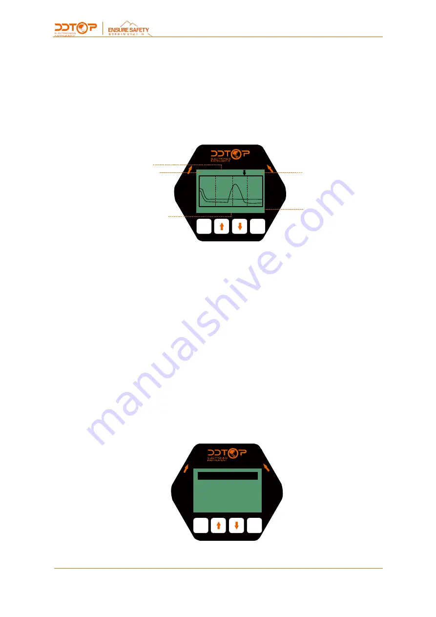
8.3 Echo Screen 

ESC

ENT

O

PE

N

LO

CK

36     3.206         2.210

0.00         dB        30.00

Echo Intensity

Real Time Value

 Echo Intensity Unit

Damping Value

Range


Figure 14 Schematic diagram of the echo interface 


Switch to main screen 

UP

Switching of the return intensity display units (dB/modal value) 

DN

Show/hide threshold curves 

ENT

NULL 

Return strength: The number indicates the maximum return strength within the range. With 

a good metal reflector, the return strength should be around 90dB, if the return strength is less 

than  30dB,  it  indicates  a  weak  return  signal  and  requires  the  technician  to  carry  out  the 

corresponding troubleshooting. 

Real time value: The real time and damping values of the echo interface are not affected by 

the  [Sensor  type]  setting  and  always  give  distance  information,  pointing  to  the  selected  echo 

wave crest. 

Echo  strength  unit:  indicates  the  signal  strength  of  the  echo  currently  selected  by  the 

algorithm. Due to the noise floor rising near the end of the FMCW itself, the echo strength and 

echo strength units are not necessarily the same. 

8.4 

Setup Screen 

ESC

ENT

O

PE

N

LO

CK

Basic Setup

Display

Diagnosis

Major Setup


Figure 15 Diagram of the setup screen 

ESC

Access to the main screen 

Summary of Contents for TRG8081

Page 1: ...1 18 WWW DDTOP COM TRG808X SERIES 80GHz RADAR LEVEL METER Product Instructions TRG808X DT JS 1052 2021 A ...

Page 2: ...hout notice Dandong Top Electronics Instrument Group Co Ltd reserves the right to modify the products described in this manual at any time without prior notice Quality Assurance Dandong Top Electronics Instrument Group Co Ltd guarantees that all products will be free from defects in materials and manufacturing processes within one year from the date of leaving the factory During the warranty perio...

Page 3: ...nstrument Group Co Ltd has passed the ISO9001 quality system certification The entire production process is strictly implemented in accordance with the scope of the quality system providing the strongest guarantee for the quality of products and services ...

Page 4: ...cal Parameters 6 3 1 Appearance and Parameters 6 3 2 Explosion proof Signs 7 4 Outline Dimension Diagram 7 5 Unpacking and Inspection 9 5 1 Precautions for Unpacking Inspection 9 5 2 Check Content 10 6 Installation 10 6 1 Installation Tools 10 6 2 Installation Requirements 10 7 Electrical Wiring 12 8 Instrument Configuration 13 8 1 Key Descriptions 13 8 2 Measurement Interface 13 8 3 Echo Screen 1...

Page 5: ...ple 80GHz radar level meter uses frequency modulated continuous wave FMCW technology to transmit a high frequency FM radar signal through the antenna which propagates in space at the speed of light and is received by the antenna when it encounters the surface of the measured medium and part of its energy is reflected back The frequency difference between the transmitted signal frequency and the re...

Page 6: ...easuring range 0 08m 10m 0 08m 30m 0 3m 60m 0 3m 120m Power supply 12 28V DC Accuracy 1mm 1mm 3mm 5mm Beam angle 3 Output signal 4 20mA HART RS485 Modbus RTU Ambient temperature 40 70 IP rating IP67 Housing material Aluminum alloy Process temperature 40 200 Process pressure 0 1 2 5 MPa TRG8083 Antenna structure Anti corrosion antenna Measuring range 0 08m 10m 0 08m 30m 0 3m 60m 0 3m 120m Power sup...

Page 7: ...4 20mA HART RS485 Modbus RTU Ambient temperature 40 70 IP rating IP67 Housing material Aluminum alloy Process temperature 40 1000 Process pressure 0 1 10 MPa 3 2 Explosion proof Signs Pass national level explosion proof certification Intrinsically safe Ex ia IIC T1 T5 T6 Ga Ex iaD 20 T85 C Intrinsically safe and explosion proof composite type Ex d ia ia Ga IIC T1 T5 T6 Gb Ex tD A21 T105 T85 3 3 Im...

Page 8: ...8 18 WWW DDTOP COM Figure 1 TRG8081 Normal tempe rature High tempe rature Figure 2 TRG8082 Connection flange Small antenna Connection flange Standard antenna Figure 3 TRG8083 ...

Page 9: ...gure 6 Radar Level Meter Model Explosion proofRating Ex iaⅡCT1 T5 T6 Ga Ex ia D 20 T85 Explosion proof Certificate No CCRI 17 2020X Explosion proofRating Ex d ia ia Ga ⅡC T1 T5 T6 Gb Ex tD A21 T100 T85 Explosion proof Certificate No CCRI 18 1038X Output Signal Accuracy Antenna Form Connection Method AmbientT emperature 40 80 T1 T5 40 60 T6 IP Rating IP67 Medium OperatingPressure MPa OperatingT emp...

Page 10: ...nge bolts for process joints 6 2 Installation Requirements Installation Position When mounting take care to keep the instrument at least 200 mm away from the vessel wall Figure 7 Reference surface Central container or axis of symmetry Figure 7 Installation Position Diagram For conical vessels with a flat tank top the best mounting position for the instrument is in the center of the top of the capa...

Page 11: ...ed or heated tanks the cable sealing sleeve should be tightened to protect against moisture and the cable should be bent downwards at the entry point Figure 9 Figure 9 Damp proof Wiring Schematic Diagram Container Receiver The length of the vessel receiver should be such that the end of the antenna extends into the tank as far as possible Figure 10 ...

Page 12: ...inal 2 Connected to the positive terminal of 24VDC Terminal 3 Loop current test used in conjunction with terminal 2 Terminal 2 and 3 are connected to an ammeter to measure the loop output current Figure 11 4 20mA Wiring Diagram Output signal RS485 Terminal 1 Connected to 24VDC negative Terminal 2 Connected to 24VDC positive Terminal 6 Connected to RS485 A Terminal 5 Connected to RS485 B ...

Page 13: ... 0001 Communication Status Unit Current Value Fault Code Damping Value Real Time Value Temperature Model Figure 13 Diagram of the measurement interface ESC 一 Access to the settings screen UP 一 Access to the parameter overview screen DN 一 Streamlined main interface ENT 一 Access to the echo screen Real time value Indicates the result of a process quantity level air height distance measured by the sy...

Page 14: ...ain screen UP 一 Switching of the return intensity display units dB modal value DN 一 Show hide threshold curves ENT 一 NULL Return strength The number indicates the maximum return strength within the range With a good metal reflector the return strength should be around 90dB if the return strength is less than 30dB it indicates a weak return signal and requires the technician to carry out the corres...

Page 15: ...esponds to a full material position and the low level corresponds to a short position ESC ENT O P E N L O C K High Low Adjustment Low le vel High le vel 0 000 30 000 m m Default 100 Default 0 High Level Adjustment Low Level Adjustment Sensor Reference Point Range Distance Height Level Figure 16 Low Level Adjustment Editing Screen With Definitions Example Tank to be measured tank height 5m then hig...

Page 16: ...reen Commonly Used Professional Menu Settings False Echo Learning False Echo Learning learns false echoes from containers containing known obstacles and forms a screening curve for background noise threshold curve TVT This option contains two levels of guidance menus False Echo Mode and False Echo Region The False echo mode can be selected in three ways 1 Full means that the false echo learning is...

Page 17: ...e fixing screws using a tool 9 4 The operating temperature range of the electronic components is 40 C to 70 C and the temperature range of the LCD display is 20 C to 70 C outside the range the LCD does not display remote transmitter is normal 9 5 Tighten the display and power supply cover after configuration to prevent the instrument from getting water and moisture 10 Fault Analysis and Troublesho...

Page 18: ...18 18 WWW DDTOP COM 11 2 Waste Disposal Please follow the current regulations in each region for waste disposal ...

Reviews: