background image

4.

If you are installing your keg refrigerator under a


counter you will need to drill 5 holes in the counter top


to mount the tower. 

1

2

" diameter


hole located at the center of the tower for the beer 

line,


locate approximately 13

1

2

" (34.3 cm) from the 

front


edge of the counter top (based on a counter top 

depth


of 25

5

16

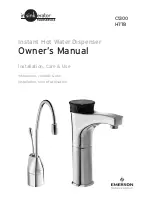
"). Next drill the 4 tower mounting holes 

per the


dimensions in Figure 2

2

. The hole diameter is 

depen-dent on the counter top material and if screw 

anchors


are required. The screws supplied are in the 

literature


pack and are a #10 x 1" type AB stainless 

steel screw.


Mark and cut the rectangular cut out for 

the drain


sump. After the holes are drilled and the keg


refrigerator is in place under the counter top feed the


beer line through the tower gasket, the 1

1

2

" hole in the


counter top and the hole in the top of the keg


refrigerator. Mount the tower to the counter top with


the 4 screws provided.

5.

Mount the regulator to the CO

2

 tank (connection 

B

 ). 

Note that the regulator has left hand threads and has


to be turned counterclockwise to tighten. Tighten with


the adjustable wrench or the 1

1

8

" open end wrench.

6.

Connect the red air line(s) from the regulator to the


large


large


hose clamp (connection 

C


).

7.

Connect the clear beer line from the tower to the 

small


small


hose


clamp (connection 

A


).

12

Diameter 

to suit

Rear of counter top

2

7

8

"

(7.3 cm)

1

3

8

"

(3.5 cm)

typical

1

1

2

 (38 mm) 

Diameter

counter 

top depth

25

5

16

"

(64.3 cm)

Figure 2

2

Figure 2

3

Figure 2

4

Tower

!

CAUTION

USING YOUR BEER DISPENSER

4¼”

(10.8 CM)

6⅜”

(16.2 CM)

6⅛”

(15.6 CM)

12¼”

(31.1 CM)

¼” (6 MM)

radii,

typical

The cutout dimensions shown in Figure 2

2

 are based on a 

25

5

16

" (64.3 cm) deep counter top. Your counter top may 

be different than this and require other front to back dimen-

sioning. Refer to the product dimensions on page 8 when  

determining the required dimensions.

Grate from 

top of beer

dispenser

Counter top

sump from

literature pack

Summary of Contents for RF24BTL2

Page 1: ...RF24TR2 RF24TL2 RF24BTR2 RF24BTL2 OUTDOOR BEER DISPENSER USER INSTALLATION GUIDE US CA ...

Page 2: ... Safety Instructions Warnings and safety instructions appearing in this guide are not meant to cover all possible conditions and situa tions that may occur Common sense caution and care must be exercised when installing maintaining or operat ing this appliance Recognize Safety Symbols Words and Labels WARNING WARNING You can be killed or seriously injured if you do not follow these instructions CA...

Page 3: ...Leave the shelves in place so children may not easily climb inside Remove Interior Packaging Your appliance has been packed for shipment with all parts that could be damaged by movement securely fastened Remove internal packing materials and any tape holding in ternal components in place The owners manual is shipped inside the product in a plastic bag along with the warranty registration card and ...

Page 4: ... openings kept clean See Figure 1 The use of a custom made grille is not recommended as it may restrict air flow INSTALLING YOUR APPLIANCE Leveling Legs Adjustable legs at the front and rear corners of the appli ance should be set so the unit is firmly positioned on the floor and level from side to side and front to back The overall height of your appliance may be adjusted between the minimum 333 ...

Page 5: ...l codes and ordinances see Figure 5 If the circuit does not have a grounding type receptacle it is the responsibility and obligation of the customer to provide the proper power supply The third ground prong should not under any cir cumstances be cut or removed INSTALLING YOUR APPLIANCE Figure 3 Figure 4 Do not remove ground prong Electrical Shock Hazard Do not use an extension cord with this appli...

Page 6: ... the marks on the floor so the side of the bracket lines up with the side of the cabinet mark and the V notches on the anti tip bracket line up with the end of the 211 2 54 6 cm line Rear of cabinet line 5 Fasten the anti tip bracket to the floor using the supplied screw See Figure 7 6 Slide the cabinet back into position making sure the rear cabinet leveling leg slides under the anti tip bracket ...

Page 7: ...tches in bracket V notches in bracket When the floor mounted anti tip bracket is used the mini mum adjusted height of the cabinet is increased by 3 8 9 mm Figure 7 Front of cabinet line Rear of cabinet line Figure 7a 211 2 54 6 cm Rear Leveling leg Screw Side of cabinet line ...

Page 8: ...37 8 60 7 cm 333 4 to 343 4 85 7 to 88 3 cm 2323 32 60 2 cm 261 4 66 7 cm 4613 32 117 9 cm 261 4 66 7 cm PRODUCT DATA MODEL ELECTRICAL REQUIREMENTS PRODUCT WEIGHT RF24T RF24BT 115V 60Hz 15A 140 lbs 63 6 kg Figure 9 211 2 54 6 cm 121 4 31 1 cm 1115 16 30 3 cm 11 27 9 cm Figure 8 Depth dimension of rough in opening may vary depend ing on each individual installation To recess entire door F dimension...

Page 9: ...lease The oF oC symbol will flash briefly after 5 seconds Interior light and display will go dark and remain so until user resets mode unit continues to operate Disable Sabbath Mode Press hold for 5 seconds and release Display and interior light return to normal operation Showroom Mode Hold and for 5 seconds Display will show for 2 seconds Interior light and display will function normally but the ...

Page 10: ...bon dioxide may be present Leave the area immediately The CO2 tank must always be connected to the regulator Never connect the tank to the keg The CO2 tank must be securely mounted in the upright position Secure it with the chain pro vided Never drop or throw the CO2 tank Keep the CO2 tank away from heat Ventilate the area after a CO2 leak WARNING 1 Remove shelving and packaged components from the...

Page 11: ...r Keg Coupler Keg Coupler Single Dispense Tower Double Dispense Tower A C Hose clamps use for connections and A C Hose clamps use for connections and A A Single Dispense Tower Kit Connect to etc A A Double Dispense Tower Kit Connect to etc Figure 11 Figure 12 Figure 13 Figure 18 Figure 19 Figure 21 Figure 17 Figure 15 Figure 16 USING YOUR BEER DISPENSER ...

Page 12: ...or Mount the tower to the counter top with the 4 screws provided 5 Mount the regulator to the CO2 tank connection B Note that the regulator has left hand threads and has to be turned counterclockwise to tighten Tighten with the adjustable wrench or the 11 8 open end wrench 6 Connect the red air line s from the regulator to the large large hose clamp connection C 7 Connect the clear beer line from ...

Page 13: ...fy the cou pler is in the OFF position see Figure 26a Align the lugs on the keg with the corresponding openings on the keg coupler and turn clockwise until the coupler stops about 90 Push down and twist the top of the coupler clockwise to allow gas to enter the keg Figure 25 Chain The chain is fastened and taped to the top of the interior liner Remove the tape and secure the CO2 tank in place in t...

Page 14: ...w 8 Tighten the locknut with the 1 2 open end wrench by turning clockwise CO2 Regulator Single Dispense Tower Your beer dispenser comes equipped with a 5 pound CO2 tank and a single gauge regulator The gauge reads the pressure being supplied to the beer keg Follow the proce dure below to adjust the pressure to 12 14 psi 0 8 to 1 bar for lager beer or 9 12 psi 0 6 to 0 8 bar for ale s To adjust the...

Page 15: ...n a free standing beer dispenser remove the grate from in front of the tower clean with soap and water and dry before reinstalling Clean the sump area with soapy water On a built in beer dispenser remove the grate and coun ter top sump clean with soap and water and dry before reinstalling Clean the sump area with soapy water and dry See Figure 31 Counter top sump Clean and dry sump area Figure 31 ...

Page 16: ...lose the gas valve s below the regulator remove both the red gas line s and clear beer line s from the keg coupler s by remov ing the plastic hose clamps See Figure 32 Soak and brush the keg coupler in hot water or a sanitizing solution Rinse thoroughly with clean water Dry all parts and reassemble CAUTION SHOCK HAZARD Disconnect electrical power from the appliance before cleaning with soap and wa...

Page 17: ...Remove faucet on tower see page 16 c Beer lines will gravity drain d Clean beer line tubing 12 Remove the front toe grille see Figures 36 and 37 and use a brush and vacuum to clean dirt and debris from beneath the unit 13 Thoroughly clean the toe grille and re install on the unit 14 Remove the rear access cover see Figure 38 and use a brush and vacuum to clean dirt and debris from the machine comp...

Page 18: ...ughly clean the exterior with a cleaner approved for stainless steel Do not use any abrasive cleaners or scouring pads 20 Any mounting hardware fasteners that are showing signs of corrosion should be replaced 21 Once the exterior has been thoroughly cleaned you may want to apply a coating of car wax to help protect against spotting from moisture dirt and debris that may accumulate on the surfaces ...

Page 19: ... replaced Frequency of cleaning will depend upon the installation location environmental and usage conditions Choosing a Cleaning Product The choice of a proper cleaning product is ultimately that of the consumer and there are many products from which to choose Depending upon the type of cleaning and the degree of contamination some products are better than others Typically the most effective and ...

Page 20: ...lation for the refrigeration system to expel heat 4 Plug your appliance into a dedicated power circuit Not shared with other appliances 5 When initially loading your new product or whenever large quantities of warm contents are placed within refrigerated storage compartment minimize door openings for the next 12 hours to allow contents to pull down to compartment set temperature 6 Maintaining a re...

Page 21: ...nt grille See clearances on page 4 Check door alignment and or replace door gasket Appliance too cold See Adjusting the Temperature on page 9 Control set too cold Door gasket not sealing properly Adjust temperature warmer Allow 24 hours for temperature to stabilize Check door alignment and or replace door gasket Noise or Vibration Appliance not level Fan hitting tube obstruction Level appliance se...

Page 22: ...or ordinary single family home use All service under this Limited Warranty shall be provided by Fisher Paykel Appliances Inc or its Authorized DCS Service Agent during normal business hours Limited Warranty How Long Does this Limited Warranty Last Our liability under this Limited Warranty expires One Year from the date of purchase of the Product by the first con sumer Our liability for repair of d...

Page 23: ...al DCS Authorized Service Agent or believe the Product is defective and wish service under this Limited Warranty please contact your dealer or call us at TOLL FREE 1 888 936 7872 or contact us through our web site www dcsappliances com You may be required to provide reasonable proof of the date of purchase of the Product before the Product will be serviced under this Limited Warranty Commercial us...

Page 24: ...ge at any time The product specifications in this guide apply to the specific products and models described at the date of issue Under our policy of continuous product improvement these specifications may change at any time For current details about model and specification availability in your country please go to our website or contact your local Fisher Paykel dealer ...

Reviews: