background image

dCS P8i

 Mk2 User Guide 

Guide for Software Issue 2.0x 

Data Conversion Systems Ltd. 

March 2011 


Manual filename: dCS P8i User Guide v2_0x.docx 

Page 11


English version 


www.dcsltd.co.uk


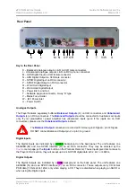
Word Clock Input / Output 

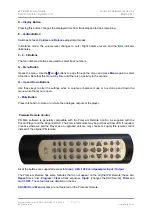
When playing a disc, the 

W/Clock In

 connector (Q) will accept standard 44.1kHz word clock from a 

master clock. When the Digital Inputs are in use, this input is disabled. 

When playing a disc, the 

W/Clock Out

 connector (R) carries a 44.1kHz word clock. When the Digital 

Inputs are in use, this output is disabled. 

Word clock is used for synchronisation only, it does not carry digital audio data. 

Power Link 

These connectors (S) can be linked to similar connectors on other 

dCS

 units with this feature 

(manufactured from 2004 to 2006) using a link cable. All units linked in this way may be turned on or 
off or set to standby by pressing a single 

Power

 button or sending one Remote Control command. 

Link cables are available from 

dCS

SUC

 Connector 

The 

SUC

 connector (T) is an RS232 interface, primarily used to remotely control the unit during 

automated testing. Please contact 

dCS

 for the codes to use this interface with a household automation 

system. Note that we recommend using infra-red remote control instead. 

Mains inlet 

Power is connected via a standard IEC320 connector (V), protected by a fuse (W) and isolated by a 2-
pole power switch (U). 

Summary of Contents for P9i Mk2

Page 1: ...or by any means electronic mechanical photocopying recording or otherwise without the prior written permission of dCS1 Any person who does any unauthorised act in relation to this publication may be liable to criminal prosecution and civil claims for damages Information contained in this manual is subject to change without notice and whilst it is checked for accuracy no liabilities can be accepted...

Page 2: ...dCS P8i Mk2 User Guide Guide for Software Issue 2 0x Data Conversion Systems Ltd March 2011 Manual filename dCS P8i User Guide v2_0x docx Page 2 English version www dcsltd co uk ...

Page 3: ...onnecting to the Digital Inputs 6 STEP 4 Powering up 7 STEP 5 Inserting and playing a Disc 7 STEP 6 Adding a System Clock 7 STEP 7 Using an external source 7 THE HARDWARE 8 Front Panel 8 Rear Panel 10 Remote Control 12 Fitting or replacing the Batteries in the Remote Control 12 Using the Original Remote Control 13 Premium Remote Control 14 THE MENU 15 Using the menu 16 Menu Sequence 16 Filter 16 P...

Page 4: ...er is necessary and much of the hardware has been replaced The Mk2 unit requires v2 software which has been written to suit the revised hardware DO NOT load P8i v2 software into a P8i Mk1 unit it is not compatible and will cause serious malfunctions or permanent damage The basic functionality of the P8i has been retained with some minor improvements The Player responds to the CD SACD button on the...

Page 5: ...ealer to have the unit reset Using the P8i with the wrong mains setting for your local supply may result in serious damage to the unit and will invalidate the warranty Do not attempt to reset the voltage yourself Power Cables If you wish to use a power cable other than the one supplied please ensure that it is a good fit to the mains inlet is not too fat too stiff or too heavy Mains Regenerators W...

Page 6: ...kS s digital data will appear on the AES OUT and RCA OUT connectors which can be used to drive an external DAC Connect one of the AES or RCA digital outputs on the P8i rear panel to the matching inputs of the DAC using suitable screened digital cables Press the MENU button and use the arrow buttons to scroll to the Digital Out page If this is set to Off press the MENU button to change to On Connec...

Page 7: ...ed as CD or SACD Either the CD or the SACD indicator will light In this release the unit will play the SACD layer of a hybrid disc by default The colour of the buttons changes depending on the type of disc you choose to play red for a CD layer or lilac for an SACD layer Press the Play Pause button Turn the volume to a comfortable level You should have audio Press the Play Pause button to pause pla...

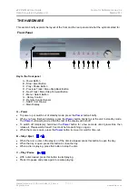
Page 8: ...out of standby mode press the Power button briefly When you have finished listening press the Power button briefly to set the unit to standby mode The Power button will glow red and the rest of the display will turn off To switch off completely hold down the Power button for a few seconds until it glows lilac then release it Please wait at least 10 seconds before switching on again When the menu i...

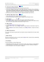
Page 9: ... F Menu Select Press the Menu button to open the menu and change or select settings in the menu When the Menu button is pressed the button lighting switches off except the menu button and the two buttons used to page forward and backwards through the menu G Rotary Control Use the Rotary Control to turn the volume up or down While the menu is open use the Rotary Control to page forwards and backwar...

Page 10: ...ced Outputs should be connected to true balanced inputs only If your preamplifier power amplifier has unbalanced inputs even if the inputs are on XLR connectors please use the Unbalanced Outputs instead The Balanced Output connectors are wired pin1 Screen pin2 Signal pin 3 Signal DO NOT connect Balanced Output pin 2 or pin 3 to ground Digital Inputs The Digital Inputs are indicated by a GREEN back...

Page 11: ... carry digital audio data Power Link These connectors S can be linked to similar connectors on other dCS units with this feature manufactured from 2004 to 2006 using a link cable All units linked in this way may be turned on or off or set to standby by pressing a single Power button or sending one Remote Control command Link cables are available from dCS SUC Connector The SUC connector T is an RS2...

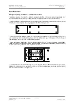
Page 12: ...battery cover To remove discharged batteries press the end back against the spring and pull that end out of the unit A small key or screwdriver may be used if the battery is a tight fit Dispose of the discharged batteries safely do not put them in the household waste To fit a new battery press the end the flat end against one of the spring contacts in the battery holder then press the battery into...

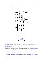
Page 13: ...tton to set the P8i to sleep mode press again to restore normal operation B SACD CD button While playing a hybrid disc the SACD layer is played by default Press the SACD CD button to change layer While changing layers and re reading the disc Loading is displayed C Player Controls The Play Pause Stop Eject Previous Track and Next Track buttons control the player in the same way as the buttons on th...

Page 14: ...s Use these keys to alter the settings when in volume or balance mode or to scroll up and down the menu when the menu is open I Mute Button Press this button to mute or un mute the analogue outputs of the player Premium Remote Control P8i Mk2 software is generally compatible with the Premium Remote Control as supplied with the Puccini Player and the Paganini DAC The Premium Remote may be purchased...

Page 15: ...CS P8i User Guide v2_0x docx Page 15 English version www dcsltd co uk THE MENU The menu gives you access to a range of additional features The chart below shows the menu sequence when playing discs When using the digital inputs the menu sequence changes as shown below to omit pages that apply to disc mode only ...

Page 16: ...ampling a CD or playing an SACD the P8i offers a choice of 4 filters The filters offer different trade offs between signal bandwidth and out of band noise level which is inherent in the 1 bit nature of DSD Filter 1 is the usual setting giving the widest bandwidth about 70kHz with the highest level of out of band noise Filter 2 gives a slightly narrower bandwidth with a lower level of out of band n...

Page 17: ...two levels 6V high or 2V low The difference between the two settings is 9 5dB For best results the P8i volume control should be set to no lower than 20 00dB for normal listening levels with typical music We suggest that you start with 2V and increase the level to 6V if this is inadequate Note that the 6V setting might be enough to overload the inputs of some preamplifiers Reduce the volume before ...

Page 18: ... the unit risk of fire or electric shock and will invalidate any warranty Replacing a Blown Fuse Referring to the diagram below remove the power cable use a small flat bladed screwdriver to pry up the tab on the fuse carrier A and pull it out Push the blown fuse out of the clip in the carrier B and dispose of it Fit a new fuse in the clip C and push the carrier back into the unit so that it clicks...

Page 19: ...unit near heat sources such as radiators air ducts power amplifiers or direct strong sunlight If in doubt the easy test is the unit is happy to work anywhere a human is If you need more help In the first instance you should contact your dealer If they cannot resolve the issue contact your national distributor or fill in the enquiry form at www dcsltd co uk page support Manufactured by Data Convers...

Reviews: