Cobalt-SS
Preparing pointwork for best performance
Use Cobalt and Alpha products for turnout or layout control and nothing is impossible any more!
The complete range of Cobalt & Alpha
products can be found on our website at
www.dccconcepts.com
Created by
DCCconcepts
MADE
in
CHINA
Cobalt-SS
Preparing the Tiebar & installing Links
We showed a little of this procedure in previous
pages but we thought a bit more detail might make
it clearer for you.
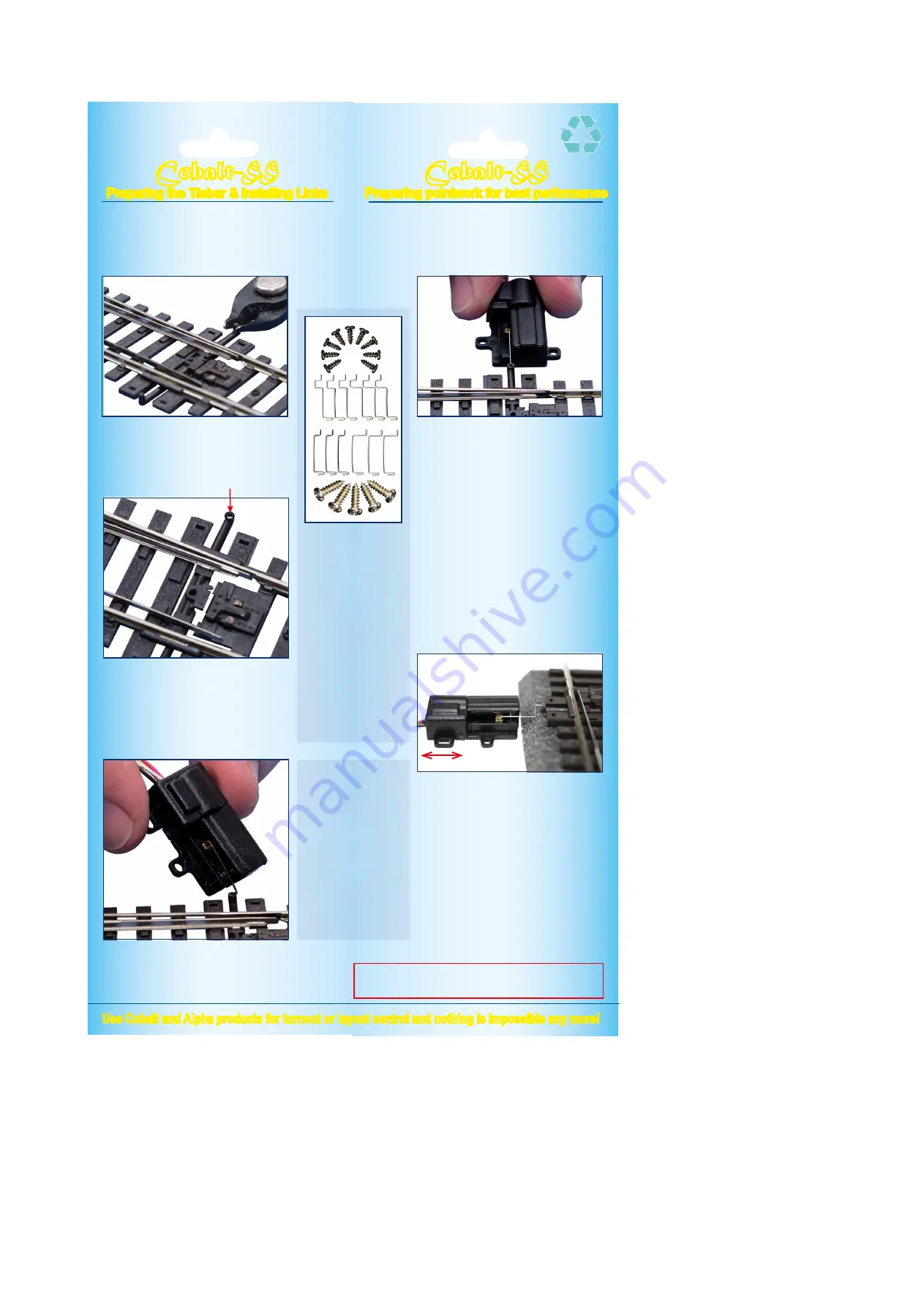
To install a Cobalt-SS link between motor and point, you will
need a small hole at the end of the tiebar (about 0.3mm or
1/64th inch). Most modellers will have the 0.3mm drill needed
for this, but if you use Peco pointwork, you won’t have to drill!
We used our DCCconcepts DCT-XTC super-sharp
track cutters but you could also use a sharp scalpel
blade. Make a neat, tidy cut, parallel to the tie-bar.
Once the small vertical pin is taken off the tie-bar,
the point will look better AND a perfectly formed
hole will be revealed, ready for a Cobalt-SS linkage
to be installed, as the image below shows!
Now we have the pointwork ready to go, it is time to
select the link you will use from the varieties that we
supply, insert it into the Cobalt-SS point motor, then in
turn, connect the link to the tiebar.
The primary diference between the links is the
relative height between the two ends of the link.
The link you choose depends on the scale of your
model - Z, N, O/HO or O etc, AND the thickness of
your trackbed!
First, insert the smaller U-shaped end of the link into the hole in
the phosphor bronze throw-bar of the Cobalt-SS motor.
Once that is done, insert the other end of the link through the
hole in the point tiebar.
(Continued top of next page)
Once the link has been inserted and you rest the Cobalt-SS on
the baseboard, the link should be close to parallel ~ horizontal.
If it is not, please consider adding a small, firm pad under the
motor before fixing it down.
It just needs to be flat & firm, so card, wood or similar, cut a little
larger than the motor and glued to the baseboard, are all OK.
Photographs above and below show a Cobalt-SS
motor with a link in place and ready to fix in place.
Note that the motor is lined up with the tiebar & that
the link is also reasonably parallel to the board.
(1) Move the Cobalt-SS motor back forth until
the far blade touches the adjacent rail.
(2) Pre-drill a small pilot hole that in the center of
the long fixing loop at each side of the motor
(3) Insert one of the black screws into each slot,
and tighten until it just touches the plastic of
the Cobalt-SS case.
(4) Using firm but gentle finger pressure on the
“Wire-end” of your Cobalt-SS motor to make
quite sure that the point blade is held firmly
against its adjacent stock rail, then tighten
each screw a just little more to fix it in place.
(5) Insert one of the black screws into each slot,
and tighten until it just touches the plastic of
the Cobalt-SS case. (do not over-tighten)
(6) Now pre-drill a small pilot hole that in the
center of the round fixing lugs at each side of
the motor and insert two more black screws.
As with the first 2 screws, do not over-tighten.
The items in the image
above are some of the
smaller items contained in
the very comprehensive
Cobalt-SS fitting kit. Every
packet includes more
linkages than motors and
we even include a spare
screw of each type
(1) These are blackened
self-tapping screws to fix
the your Cobalt-SS motors
in place on the layout.
(2) These are the four
different types of cranks
supplied in every pack. We
supply more than you will
need so that you will have
spares for later use.
(3) The silver screws are
for fixing the Cobalt-SS
control board to the layout.
1
2
3
With the installation done, connect your Cobalt-SS
motor to the control board and, after addressing or
connecting momentary or push button switches,
you can test your installation.
(1) If its OK and the throw is just right. Re-check the
screws are firm and move on to the next motor.
(2) If the throw seems too far or completes before
Cobalt-SS motor power turns off, reduce throw
by using the blue adjuster screw (1) in the dia-
gram. Lit LEDs should move from M towards S.
(3) If the throw seems too small or incomplete, then
increase the throw by using the blue adjuster
screw (1) in the diagram. The lit LEDs should
move from M towards XL.
(4) If the throw still seems uneven or incomplete,
then remove the screws from the round fixing
lugs and slightly loosen the two screws in the
longer loops. Re-centralise the motor then
repeat steps 2 and 3 until operation is perfect.
Mounting Cobalt-SS further
away from your pointwork
Easy: Simply cut one of the
links in half and solder the
ends to a little brass wire.
We have also made you a
“Distant Mounting Pack”
It is complete with springy
but easy to solder PB wire,
some tubes, some cranks
and a wide set of linkages
so you can do many clever
things with Cobalt-SS!
For the more adventurous
modeller we’re nearly ready
to launch our working point
rodding kit too, so you can
then take it to the extreme!
We are modellers first and foremost & we love to see our products
in action, so if you have the time, we’d really appreciate it if you
could send a picture to show us how you are using Cobalt-SS!


