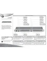


Front Panel Connections Cont’d
®
3
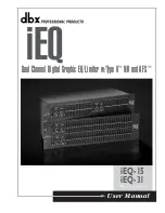
iEQ User Manual
5
Operation
iEQ
The iEQ 15 and 31 offer the exclusive patent pending AFS (Advanced Feedback Suppression)
feedback elimination module. The AFS uses Precision Frequency Detection and state-of-the-art
processing to determine the exact portions of a given frequency of your feedback that need to
be removed (instead of taking out large sections of your sound). For more detailed informa-
tion regarding AFS, please visit the AFS white paper section at www.dbxpro.com.
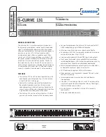
The AFS module of the iEQ 15 and 31 allow the user to optimize the elimination of feedback.
In the past, graphic equalizers were used to eliminate feedback from a system. This was an
acceptable method for eliminating feedback, but when this method was precision tested, the
result clearly showed that a single 1/3 octave EQ slider was removing approximately half of the
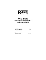
signal power. With the AFS, the module removes the feedback automatically and the propri-
etary, precision AFS filters remove only a fraction of the frequency spectrum. The following
diagram shows AFS as opposed to competing, competitive feedback eliminators and conventional
graphic EQs:
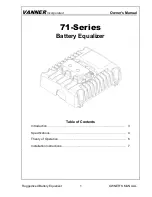
dbx Type V™ Noise Reduction
: This button engages (when lit) the dbx Type V™ Noise
Reduction circuit within the EQ. Typically, graphic equalizers raise the noise floor within the
signal path, and dbx’s proprietary Type V™ noise reduction will reduce the apparent noise floor
through its simultaneous encode/decode process (shown below). The button lights when the
dbx Type V™ Noise Reduction circuit is activated.
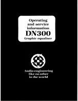
Frequency Band Slider Controls
: Each one of these slider potentiometers will boost or cut at
its noted frequency by ±6dB or ±15dB, depending upon the position of the BOOST/CUT
RANGE switch. When all the sliders are in the center detented position the output of the equal-
izer is flat. The frequency band centers of the iEQ-31 are marked at 1/3rd of an octave inter-
vals on ISO standard spacings, while the frequency band centers of the iEQ-15 are marked at
2/3rds of an octave intervals on ISO standard spacings.
Low Cut Enable
: The LOW-CUT button inserts (when lit) or removes the 18dB/octave 40Hz
Bessel low-cut filter from the signal path. When the LOW-CUT switch is pushed in, the LOW-
CUT filter is IN the audio path.
Type V™
Encode
Simultaneous Encode/Decode Control
Audio
Audio
EQ
Type V™
Decode
Competitor’s
Feedback
Elimination
1/3 Octave EQ
dbx AFS™