background image

13

223s, 223xs,

234s, 234xs

 Section 3 - Rear Panel Operations

3.1 Rear Panel Operations

The mode switches on the back panel of the unit are used to select one of the three modes 
of operation in the 234s/234xs and one of two modes of operation in the 223s/223xs. There 
could be disastrous consequences if the crossover were improperly setup or the switches were 
mistakenly pushed during the regular operation of a sound system. Therefore great care should 
be taken when setting these switches. There is a mode diagram on the back panel to help you 
understand at a glance how this is done. The following steps should be taken in setting up 
your system:
 
  •  Know the loudspeaker manufacturer’s requirements regarding the amplification needs 

of your particular speaker system. Follow the manufacturer’s guidelines carefully, as 
dbx is not responsible for damage relating to improper setup or implementation of the 
234s/234xs or the 223s/223xs.

 
  •  Without any audio or power connections in place, use the back panel switches on the 

crossover to set it to the proper mode of operation; either stereo 2-way, stereo 3-way, or 
mono 4-way for the  234s/234xs, or stereo 2-way or mono 3-way for the 223s/223xs.

 
  •  Use the literature that came with your speaker system to properly set up the mode of 

operation and crossover frequencies to the manufacturer’s specifications.

  •  There is one of the four possible mode button combinations for the 234s/234xs which is 

marked “not valid”. Be sure you have not selected this combination as the 234s/234xs 
will not operate correctly in this mode.

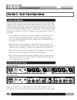
3.2 dbx 234xs/234s Rear Panels

dbx 234xs Rear Panel

dbx 234s Rear Panel

When you are certain that the proper selections have been made, complete the steps 
described below and in the “234s/234xs or 223s/223xs Audio Connections” section on page 9.

Section 3

Rear Panel Operations

8

Summary of Contents for 223xs

Page 1: ...User Manual 2 Way 3 Way 4 WayCrossovers Professional Audio Equipment...

Page 2: ...er Cord WARNING THIS APPLIANCE SHALL BE CONNECTED TO A MAINS SOCKET OUTLET WITH A PROTECTIVE EARTHING CONNECTION The cores in the mains lead are coloured in accordance with the following code GREEN an...

Page 3: ...t of Engineering 8760 S Sandy Parkway Sandy Utah 84070 USA Date November 1 2010 European Contact Your local dbx Sales and Service Office or Harman Music Group 8760 South Sandy Parkway Sandy Utah 84070...

Page 4: ......

Page 5: ...Mono 4 Way Mode 5 2 2 dbx 223s 223xs Front Panel 6 Stereo 2 Way Mode 6 Mono 3 Way Mode 7 Section 3 Rear Panel Operations 8 3 1 Rear Panel Operations 8 3 2 dbx 234xs 234s Rear Panels 8 3 3 dbx 223xs 22...
Page 6: ...sticker attached to the bottom panel If you have not already taken the time to fill out your warranty registration card and send it in please do so now Before you return a product to the factory for...

Page 7: ...ZATION from the factory where all parts and labor will be covered up to a period of two years A Return Authorization number must first be obtained from dbx by telephone The company shall not be liable...

Page 8: ...requency output level with a range of to 6 dB 4 8 High Output Controls the High frequency output with a range of to 6 dB 9 14 Low Cut Switch for selecting the 40 Hz high pass filter An LED indicates t...

Page 9: ...ut Controls the Mid Frequency output with a range of to 6 dB 6 12 High Output Controls the High Frequency output with a range of to 6 dB 13 19 Low Cut Switch for selecting the 40 Hz high pass filter A...

Page 10: ...r point between HIGH MID and HIGH frequencies 7 High Mid Output Controls the HIGH MID frequency output level with a range of to 6 dB 8 High Output Controls the HIGH frequency output level with a range...

Page 11: ...h Selects crossover point between the LOW and HIGH outputs 3 7 Low Output Controls the Low Frequency output level with a range of to 6 dB 4 8 High Output Controls the High Frequency output with a rang...

Page 12: ...t level with a range of to 6 dB 6 High Output Controls the HIGH frequency output level with a range of to 6 dB 7 Low Cut Switch for selecting the 40 Hz high pass filter An LED indicates the selection...

Page 13: ...dbx is not responsible for damage relating to improper setup or implementation of the 234s 234xs or the 223s 223xs Without any audio or power connections in place use the back panel switches on the cr...

Page 14: ...sed This designation applies only to that mode of operation 3 3 dbx 223xs 223s Rear Panels dbx 223xs Rear Panel dbx 223s Rear Panel The 223s 223xs is marked in a similar way for stereo 2 way operation...

Page 15: ...rossover first then to a power source that is properly grounded Never lift the ground as a shock hazard may result After you have safely plugged in the crossover turn on the source device s Turn the a...

Page 16: ...oth the left and right inputs The sum is sent to channel one s low output marked LF SUM while channel two s low output is not used and channel two s phase invert led is disabled indicating it is not o...

Page 17: ...k the LF Sum switch Check the x10 switch This changes the range of the crossover frequency from 45 960 Hz to 450 Hz 9 6 kHz HUM AND OR BUZZ If you suspect that the hum is caused by a ground loop Syste...

Page 18: ...to 2 k or greater OUTPUT 223xs 234xs Connectors XLR Type Electronically balanced unbalanced RF filtered Impedance Balanced 60 unbalanced 30 Max Output Level 20 dBu balanced unbalanced into 600 or grea...

Page 19: ...Low Cut Activates 40 Hz Butterworth 12 dB octave high pass filter one switch per channel Phase Invert Inverts the phase at the output one switch per output Rear Panel x10 Multiplies crossover frequen...

Page 20: ...8760 South Sandy Parkway Sandy Utah 84070 Phone 801 568 7660 Fax 801 568 7662 Int l Fax 801 568 7583 Questions or comments Contact us at www dbxpro com Printed in China 18 0808 A...

Reviews: