


24
VIO W15T
Cod. 420120335 REV. 1.0
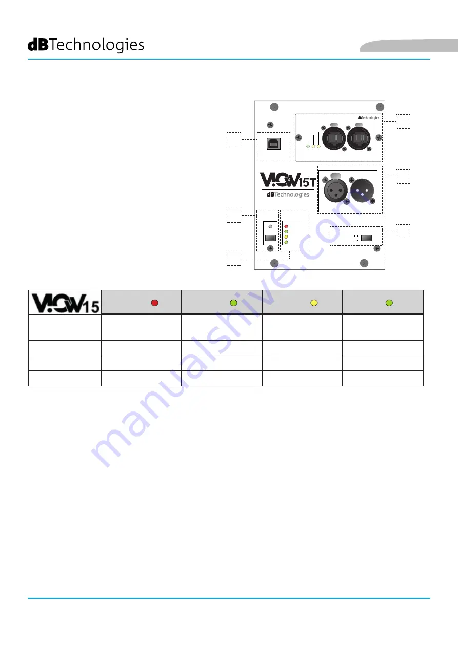
INPUT, OUTPUT AND CONTROL SECTION
1. USB SERVICE DATA
Using this standard type B USB port, you can update
the product's firmware using a PC and USB BURNER
MANAGER. For further information, refer to the
website http://www.dbtechnologies.com in the
“
DOWNLOADS
” section and the chapter
UPDATING
THE FIRMWARE.
2. SYSTEM TEST
With this control you can check the status of the
transducers using the integrated impedance test.
3. STATUS LEDs
The LEDs provide an immediate indication of the
status of the monitor, in accordance with the logic
summarised in the following table:
Limiter
Signal
Status
On
Power up
OFF
OFF
STEADILY LIT FOR A
FEW SECONDS
OFF
Use
ACTIVE
ACTIVE
OFF
STEADILY LIT
Partial malfunction
ACTIVE
ACTIVE
CYCLICALLY LIT
STEADILY LIT
Total malfunction
CYCLIC FLASHING
OFF
STEADILY LIT
OFF
4. RDNet NETWORK CONECTION INPUT AND LINKING, RDNet STATUS LEDS
Section compatible with network cables fitted with etherCON/RJ45 connectors. In particular:
•
“Data In” must be connected to devices such as RDNet Control 2 or Control 8
•
“Data Out” is used to link the network to other devices in a daisy-chain configuration
The LEDs indicate the network (RDNet) operating status of the monitor.
In particular:
•
“Link” illuminates to indicate that the RDNet network is active and has recognised the device
•
“Active” flashes to indicate the presence of data traffic
•
“Remote Preset Active” signals that all the local controls on the amplifier panel are bypassed
by the RDNet remote control
PPU
USSH
H
Data Out
Data In
R
RD
DN
Neett
Link
Active
Remote
Preset Active
Expansion Card
PUSH
PUSH
Input
Output
Link
Balanced Audio
ON
Limiter
Signal
Status
Push and Hold
Service/User
Flat
System
Test
Status
DSP Preset
USB Data Service
1
2
3
4
5
6
English


