www.dbtechnologies.com
VIO S318
Rev 1.2 cod. 420120244Q
3) First switch on
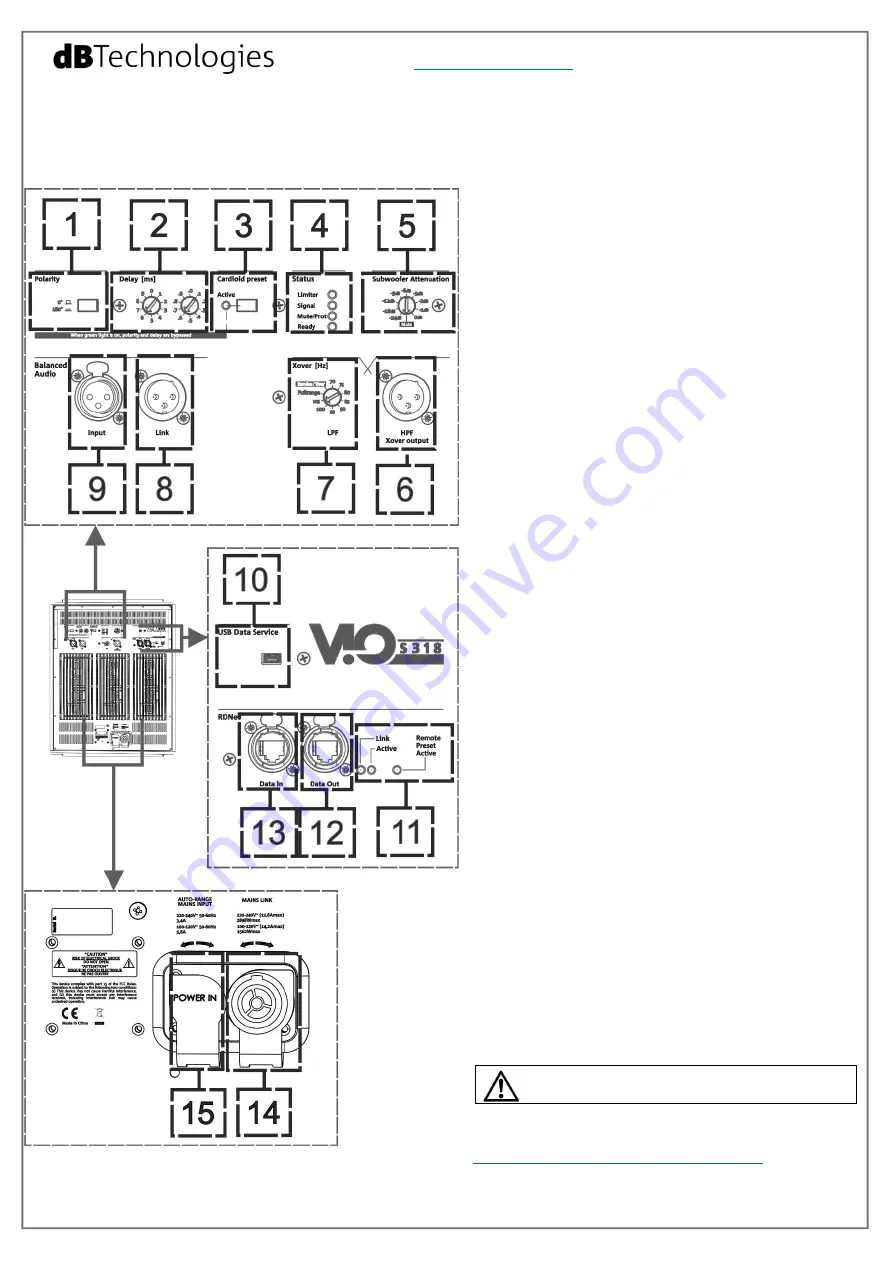
The 3 DIGIPRO G3 amplifiers of VIO S318 are controlled
by a powerful DSP. All the connections and controls are
in the rear amplifier control panel:
1 – Polarity switch
2 – Delay rotary controls
3 – Cardioid preset switch
4 – Status LEDs (Limiter, Signal, Mute/Protection,
Ready)
5 – Subwoofer attenuation rotary control
6 – HPF Xover (balanced) output
7 – Xover rotary control
8 – Link (balanced) connector
9 – Input (balanced) connector
10 – USB Data Service
11 – RDNet status LEDs
12 – RDNet Data Out
13 – RDNet Data In
14 – Mains Link connector
15 – Auto-Range Mains input connector
a)Once you have properly set up the desired
configuration (see also the VIO S318 complete user
manual and accessories instructions for further
information), connect the audio input (
9
). Set the
Subwoofer attenuation (
5
) to the desired level.
b) Connect the possible output direct link (
8
), and/or
HPF Xover output (
6
). Set the Xover rotary control (
7
)
to the correct frequency. This filter acts on internal
transducers and on HPF Xover output (
6
), It does not
affect the link (
8
) output.
c) Choose the Subwoofer Setup (Polarity and Delay
1,
2
) to obtain the correct behavior. In cardioid
configuration, please note that the cardioid preset
switch (
3
), when active, bypass Polarity and Delay
controls.
d)
In case of remote control, connect the Data Input
(
13
) to the hardware remote controller (RDNet Control
2 or RDNet Control 8) with cables equipped with
etherCON connectors. Then connect the Data Output
(
12
) to the Data Input (
13
) of a possible second device,
and so on. When the RDNet network is on and it has
recognized the connected device, the LED “Link” (
11
) is
on. The other LEDs (
11
) “Active” start blinking at the
presence of data transmission, the “Remote Preset
Active” advise that all the local controls set on the
amplifier panel (level, DSP presets, etc.) are by-passed
and controlled remotely by RDNet.
In remote control it is essential the use of free
dBTechnologies software:
•
dBTechnologies Network,
useful for an in-depth control of different devices in
remote connection;
•
dBTechnologies Composer,
useful for the complete sound system design for
various professional needs, particularly developed for
VIO series.
e)
Connect the power supply (
15
). It is possible to link
up to 4 VIO S318 at 220V-240V, or 3 VIO S318 at 100-
120V with the related mains link connector (
14
).
In configurations with more than one VIO S318, please pay
attention to inrush current.
For further information, download the complete user
manual and the free software:
www.dbtechnologies.com/EN/Downloads.aspx
or scan the QR code.


