Day and Night R4H3 Installation Instructions Manual Download Page 11

INSTALLATION INSTRUCTIONS

R

410A Split System Heat Pump

428 01 5302 00

11

DEFROST SYSTEM

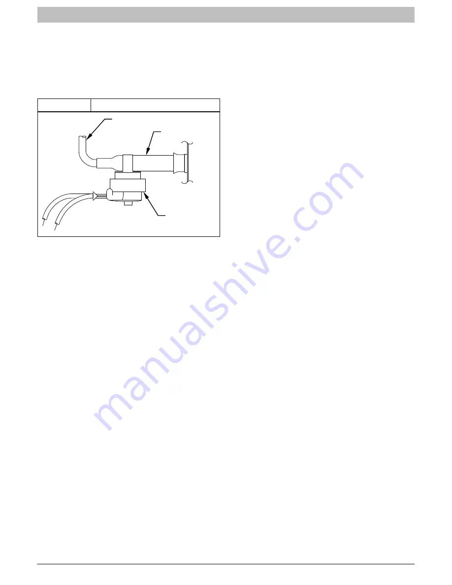
A. DEFROST THERMOSTAT

The defrost thermostat is factory installed on a short tube

stub extending from the coil end plate. Refer to Figure 11

and confirm that the thermostat is securely fastened in

place on the tube stub.

Figure 11

Defrost Thermostat

FEEDER TUBE

TUBE STUB

DEFROST

THERMOSTAT

COIL

B. DEFROST CONTROL BOARD

The defrost board is a time/temperature control which

includes a field

selectable time period between defrost

cycles of 30, 60, or 90 minutes (quick

connects located

at board edge, factory set at 60 minutes).
Defrost mode is identical to cooling mode except that

outdoor

fan motor stops and second

stage heat is

turned on to continue warming conditioned space.
Initially, the defrost cycle timer starts when the contactor

is energized and a 24 VAC signal is present on the T1

terminal. Then the defrost cycle begins when the defrost

thermostat is closed and the cycle timer times out (30, 60,

90 or minutes).
There are two 

timers

 involved in the defrost sequence:

Interval Timer

 – 30, 60, or 90 minutes, selected by

setting the jumper on the defrost board. Timer is only

active during calls for heating. Timer starts when the

defrost thermostat closes 32

°

F (0

°C

). Timer stops when

a defrost is initiated by the defrost board or when the

defrost thermostat opens 65

°

F (18

°

C).

Defrost Timer

 – 10 minutes, not adjustable. Timer is only

active while the coil is defrosting. Timer starts when the

defrost board initiates a defrost. Timer stops when the

defrost thermostat opens 65

°

F (18

°

C) or after timing out

at 10 minutes (whichever comes first).

SPEEDUP

 pins are provided on the defrost board to help

in troubleshooting without waiting for timers to expire.

Jumpering the SPEEDUP pins causes any active timer to

run very fast (256 times normal speed). Jumpering the

SPEEDUP pins does not by itself initiate any timers, it

only affects timers that are already running or are already

part of the sequence.
To initiate a forced defrost cycle (test cycle), the defrost

thermostat (Figure 11) must be closed.
There are two ways to verify that the defrost thermostat

is closed:

1. Jumper across the DFT terminals on the defrost

board (Figure 12). With this method, the defrost

thermostat is removed from the circuit, and operation

of the defrost thermostat itself will not be observed.

Skip to #3.

2. Use a volt-meter to confirm there is no voltage across

the DFT leads. 24 volts across the SFT terminals

indicates an OPEN defrost thermostat. Zero volts

across the DFT terminals indicates a CLOSED defrost

thermostat.

With this method, the operation of the defrost

thermostat can be observed during the test. If the

defrost thermostat is confirmed closed, skip to #3.

If the defrost thermostat is open (24 volts across DFT

leads) it may be possible to close the defrost thermostat

by forcing a frost buildup on the outdoor coil. Follow

these steps:

S

Turn off power to unit.

S

Disconnect outdoor fan-motor lead from OF2 on

control board (Figure 12). Tape lead to prevent

grounding.

S

Restart unit in heating mode; wait for

accumulation of frost on outdoor coil. Use

volt-meter to confirm there are zero volts across

the DFT leads (thermostat closed).

S

Turn off power to unit. Replace outdoor fan-motor

lead to OF2 on control board (Figure 12). Restart

the unit in heating mode.

3. With unit running in heating mode and the defrost

thermostat closed, the entire defrost sequence can

be sped up for testing by shorting together the

SPEEDUP pins on the defrost board. Use a

flat-headed screwdriver to short the pins together.

4. Hold the SPEEDUP pins shorted together until the

reversing valve shifts.

SPEEDUP reduces whatever time was left on the

interval timer (30/60/90 minutes). In normal operation

the reversing valve will always shift with the SPEEDUP

pins shorted for between 1 and 21 seconds.

5. After shorting the SPEEDUP pins together as

described in #4, the reversing valve will energize

(shift to AC mode), the outdoor fan will stop, the strip

heat will energize, and the coil will begin to defrost.

There are two options for the defrost test:

a. Remove the short from between the SPEEDUP

pins immediately after the reversing valve shifts,

and the unit will defrost for a shortened period of

time (something less than 10 minutes). The

defrost will stop when the defrost thermostat

opens (reaches 65

°

F)(18

°

C) or when the defrost

timer times out (something less than 10 minutes).

b. Leave the SPEEDUP pins shorted together for

more than 2 seconds after the reversing valve

shifts, and the unit will immediately return to

heating operation (#6 below). Continue to leave

the pins shorted together and the sequence

starts over at #4 above.

6. Unit returns to heating mode after defrost sequence.

Reversing valve shifts back, outdoor fan starts up,

and strip heat de-energizes.

Summary of Contents for R4H3

Page 1: ...e following manner The signal word CAUTION is used throughout this manual in the following manner Signal Words on Product Labeling Signal words are used in combination with colors and or pictures on product labels WARNING Safety Labeling and Signal Words CAUTION WARNING TABLE OF CONTENTS Inspect New Unit 2 Safety Considerations 2 Location 2 Clearances 2 3 Unit Support 4 Refrigeration System 5 9 El...

Page 2: ...lations concerning zoning noise platforms and other issues Locate unit away from fresh air intakes vents or bedroom windows Noise may carry into the openings and disturb people inside Locate unit in a well drained area or support unit high enough so that water runoff will not enter the unit Locate unit away from areas where heat lint or exhaust fumes will be discharged onto unit as from dryer vent...

Page 3: ...l 6 152mm 24 610mm Service Wall Wall Wall 6 152mm 6 152mm Post Wall Wall 18 457mm 18 457mm 18 457mm 18 152mm 6 152mm 6 152mm 6 152mm 18 457mm 18 457mm 18 457mm 18 457mm 24 610mm Service 24 610mm Service 24 610mm Service 24 610mm Service 24 610mm Service 24 610mm Service 4 102mm 4 102mm wide fence 18 457mm 18 457mm ...

Page 4: ...latform for the unit must be level If installation is on a flat roof locate unit minimum 6 inches 152mm above roof level Place the unit over one or more load bearing walls If there are several units mount them on platforms that are self supporting and span several load bearing walls These suggestions are to minimize noise and vibration transmission through the structure If the structure is a home ...

Page 5: ...ng refrigeration tubing Tubing can kink easily and if this occurs the entire length of tubing must be replaced WARNING PERSONAL INJURY HAZARD Failure to relieve system pressure could result in personal injury and or death Relieve pressure and recover all refrigerant before servicing existing equipment and before final unit disposal Use all service ports and open all flow control devices including ...

Page 6: ...as velocity do not upsize vertical suction risers E LIQUID LINE FILTER DRIER NOTE It is recommended that an appropriate filter drier be installed in the liquid line Leave the plugs in the tube ends until the filter drier is installed The optimal location for the filter drier is close to the indoor coil Heat pump filter driers are bi flow type Either end can be pointed towards indoor coil Refer to ...

Page 7: ... CAUTION PRODUCT DAMAGE HAZARD Failure to follow this caution may result in product damage Braze with Sil Fos or Phos copper alloy on cop per to copper joints and wrap a wet cloth around rear of fitting to prevent damage to TXV H EVACUATING LINE SET AND INDOOR COIL The unit is shipped with a factory refrigerant charge The liquid line and suction line service valves have been closed after final tes...

Page 8: ...XV restricting refrigerant flow and affecting operation of the system Remove Suction service valve cap and insert a hex wrench into the valve stem Hold the valve body steady with an end wrench and back out the stem by turning the hex wrench counterclockwise Turn the stem until it just contacts the rolled lip of the valve body After the refrigerant charge has bled into the system open the Liquid se...

Page 9: ... to Figure 9 Route thermostat wiring through rubber grommet in bottom of Control Box Low voltage lead wires are provided in the control box for connection to thermostat wires use wire nuts Refer to Wiring Diagram on unit and Figure 10 for low voltage wiring examples NOTE Use No 18 AWG American Wire Gage color coded insulated 35 C minimum wire If thermostat is located more than 100 feet 30 5 m from...

Page 10: ...TALLING OUTDOOR THERMOSTATS SYSTEMS WITH ONE OUTDOOR THERMOSTAT G R W 3 C O R G R W 3 C E C W 2 Y W 2 O R C W 2 Y W 2 C L G Y E O R SYSTEMS WITHOUT OUTDOOR THERMOSTATS C G R W 2 C Y O R W 2 SUBBASE THERMOSTAT CONNECTION SPLICE INDOOR CONNECTION SPLICE OUTDOOR BOARD DEFROST SUBBASE THERMOSTAT CONNECTION SPLICE INDOOR CONNECTION SPLICE OUTDOOR BOARD DEFROST SUBBASE THERMOSTAT CONNECTION SPLICE INDOO...

Page 11: ...f the defrost thermostat itself will not be observed Skip to 3 2 Use a volt meter to confirm there is no voltage across the DFT leads 24 volts across the SFT terminals indicates an OPEN defrost thermostat Zero volts across the DFT terminals indicates a CLOSED defrost thermostat With this method the operation of the defrost thermostat can be observed during the test If the defrost thermostat is con...

Page 12: ... Defrost Control Board R8 OF1 K1 O1 R21 C2 R6 H9C1 C US R14 R13 D13 R7 C4 C10 JW2 JW1 D3 C16 C7 R28 D6 JW3 C13 R4 R1 R2 R3 R11 R5 R26 D1 D2 D10 A29 R9 D4 C19 C9 C1 OF2 CEBD430524 01A 5501A P2 1 Y T1 C C O DFT SPEEDUP P1 1 J1 1 P3 1 J2 30 60 90 W1 R20 1 HK32EA001 C17 U1 1 U3 O R W2 Y C ...

Page 13: ...th is beyond 80 feet 24 4m or greater than 20 feet 6 1m vertical separation See Long Line Guideline for special charging requirements A UNITS WITH COOLING MODE TXV Units installed with cooling mode TXV require charging by the subcooling method 1 Operate unit a minimum of 15 minutes before checking charge NOTE If outdoor unit has a 2 speed fan motor motor will operate in low speed when outdoor ambi...

Page 14: ...13 16 17 19 21 80 5 8 12 15 18 21 25 28 31 35 27 3 4 7 8 10 12 14 16 17 19 85 8 11 15 19 22 26 30 33 29 4 6 8 11 12 14 17 18 90 5 9 13 16 20 24 27 31 32 3 5 7 9 11 13 15 17 95 6 10 14 18 22 25 29 35 3 6 8 10 12 14 16 100 8 12 15 20 23 27 38 4 7 8 11 13 15 105 5 9 13 17 22 26 41 3 5 7 9 12 14 110 6 11 15 20 25 43 3 6 8 11 14 115 8 14 18 23 46 4 8 10 13 Optimum performance point 82 F 28 C outdoor am...

Page 15: ...0 84 29 82 28 80 27 308 92 33 90 32 88 31 86 30 84 29 82 28 317 94 34 92 33 90 32 88 31 86 30 84 29 326 96 36 94 34 92 33 90 32 88 31 86 30 335 98 37 96 36 94 34 92 33 90 32 88 31 345 100 38 98 37 96 36 94 34 92 33 90 32 364 104 40 102 39 100 38 98 37 96 36 94 34 374 106 41 104 40 102 39 100 38 98 37 96 36 384 108 42 106 41 104 40 102 39 100 38 98 37 395 110 43 108 42 106 41 104 40 102 39 100 38 4...

Page 16: ... ED 4X30 EA 4X30 14 17 A 3 EN 4X30 3 3 EHD4X30A 3 3 FEM4 P X 30 A TXV 3 FSA4X30 A 3 FEA4X30 A 3 FXM4X30 A 5 5 FS M U 4P30 A TXV 5 5 FVM FCM 4X36 5 3 ED 4X36 EA 4X36 14 17 21 A 5 3 EN 4X36 3 EHD4X36A 5 3 FEM4P36 A TXV FSA4X36 A 5 3 FEA4X36 A 5 3 F E X M4X36 A 5 5 FS M U 4P36 A TXV 5 3 ED 4X42 EA 4X42 21 24 A 3 EN 4X42 21 3 END4X42 17 3 EHD4X42A 5 FEM4 P X 42 A TXV 5 FXM4X42 A 5 FS M U 4P42 A TXV 5 ...

Page 17: ...st bank supplemental electric heat and providing electrical potential to the second heater sequencer if used If outdoor temperature falls below the setting of the outdoor thermostat field installed option contacts close to complete the circuit and bring on the second bank of supplemental electric heat When the thermostat is satisfied its contacts open de energizing contactor blower relay and seque...

Page 18: ...nts is only compatible with POE oils Vacuum pumps will not remove moisture from oil Do not use liquid line filter driers with rated working pressures less than 600 psig Do not install a suction line filter drier in liquid line POE oils absorb moisture rapidly Do not expose oil to atmosphere POE oils may cause damage to certain plastics and roofing materials Wrap all filter driers and service valve...

Reviews: