ENGLISH
4
Power
Supply
UTP
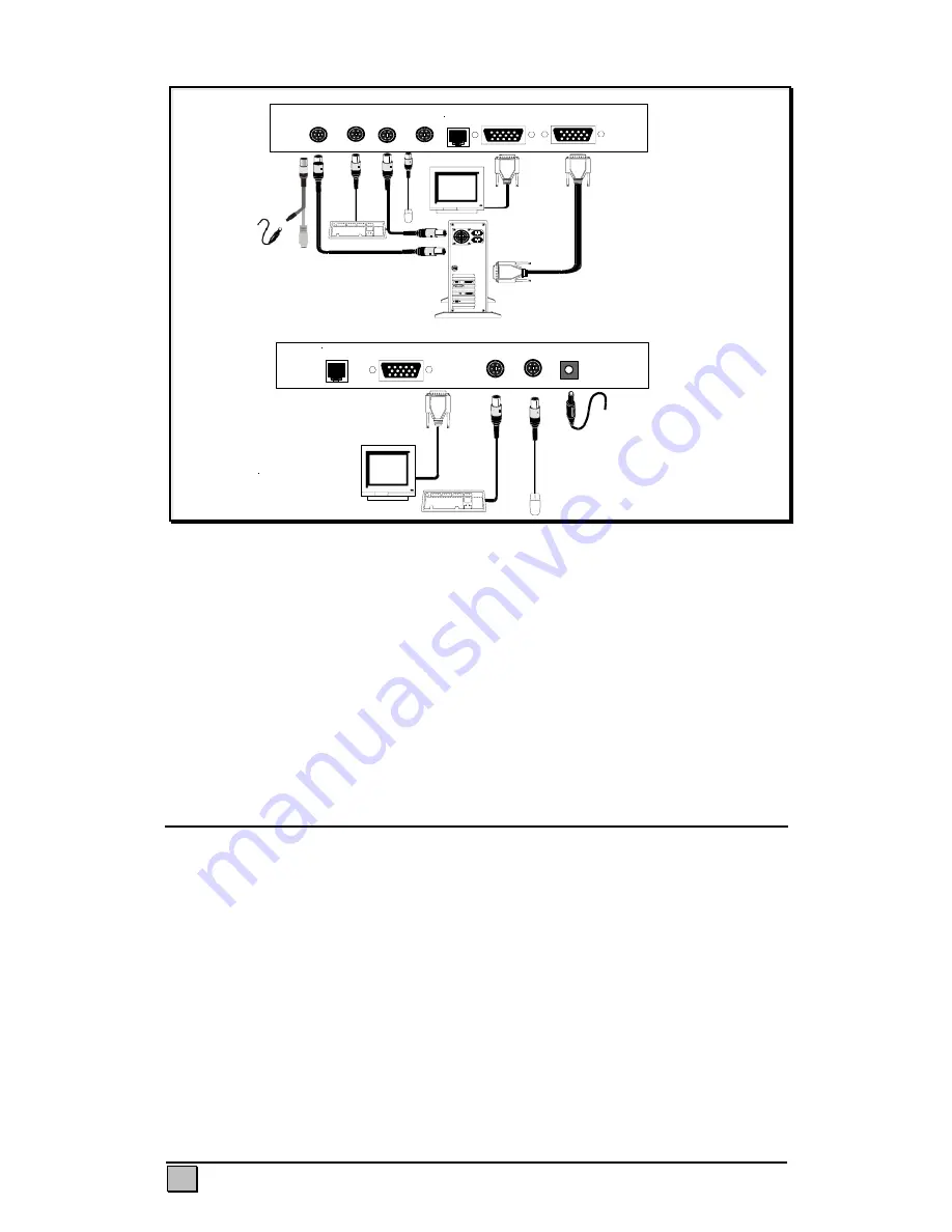
Rear View of Remote Unit
Monitor
Keyboard Mouse
9 –12V DC
Remote
Rear View of Local Unit
Keyboard
(CPU)
Keyboard
Mouse
(CPU)
Mouse
UTP
Monitor
VGA Output
(CPU)
Local
Optional 5VDC power supply
and adaptor
cable
Voyager 300
Figure 3 Connecting the Voyager 300
Note—Voyager 125H does not have the dipswitches; it is not necessary to adjust
for cable length on these models, only gain and equalizaton.
Important note on power supplies/mains adapters--
The local unit (all Voyager models) is normally powered from the keyboard connector.
Some PC’s do not supply enough power from the keyboard connector; this necessitates
the use of a 5vdc mains adapter on the local unit. The Voyager 60 is equipped with a
DC jack for this purpose; this jack is normally not used, since most PC-s supply enough
power through the keyboard connector. The Voyager 125H/300 must be connected
with a special PS2/DC adapter Y- cable which allows connection of both mains adapter
and keyboard cable through the local unit’s PC keyboard connector.
Procedure
We recommend that the complete system be tested in one room
before
permanent
installation. If a long interconnect cable is not available, use a patch lead to test
basic unit operation with your PC.
Step 1: Setting the Cable Length Dipswitches
The Voyager 60 has three gain controls to adjust gain, brightness and cable length
located on the underside of the device. The Voyager 125H use only the
equalization/gain controls and brightness on the front panel. The Voyager 300
compensates the cable length through the dipswitches on the underside of the device.
The Voyager 300 also has two rotary controls on the front panel to precisely alter the
compensation level and so ‘tunes in’ the image precisely for the cable length used.
The three cable length dipswitch sets should be set as follows:


