


Remote
Local
Selected
Active
Remote
Local
Selected
Active
Remote
Local
Selected
Active
Operations
The console is selected by the push button on the local unit. There are 3 modes of operation:-
1.
Both Consoles
– Simultaneous Operation (default)
2.
Local Console Only
3.
Remote Console Only
When the active console configuration is changed, the configuration is saved automatically and is
unaffected by the unit reset.
The active console is shown by means of LED indicators as described below.
LED Indicators
The LED indicators of remote console are the same as local if both units are connected successfully;
or all LED indicators at remote console will turn OFF
Select LED Indictors (Red)
Both Selected
The system can be controlled from both the local and remote console.
Local Selected
The system can be controlled from the local console only.
Remote Selected
The system can be controlled from the remote console only.
Active LED indicators (Green)
Local Active
When lit, indicates the connection between the local unit and computer
is ready and working.
Remote Active
When lit indicates the connection between the local and remote units is
ready and working.
Correct operation requires that both the Local and Remote Active LED’s
are lit which means that the local is connected to the computer and
working, and the connection between the local and remote units is
working.
If the active console is inconsistent with the selected console, the system cannot be controlled with
either console.
Reset
Remote
Local
Selected
Active
Remote Console
5V DC
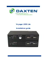
Front & Rear Panel Layout of
Voyager 100 USB Lite Remote Unit
Reset
Remote
Local
Selected
Active
Local Console
5V DC
Front & Rear Panel Layout of
Voyager 100 USB Lite Local Unit
Remote
Local
Selected
Active
Remote
Local
Selected
Active
Remote
Local
Selected
Active
Remote
Local
Selected
Active
Remote
Local
Selected
Active