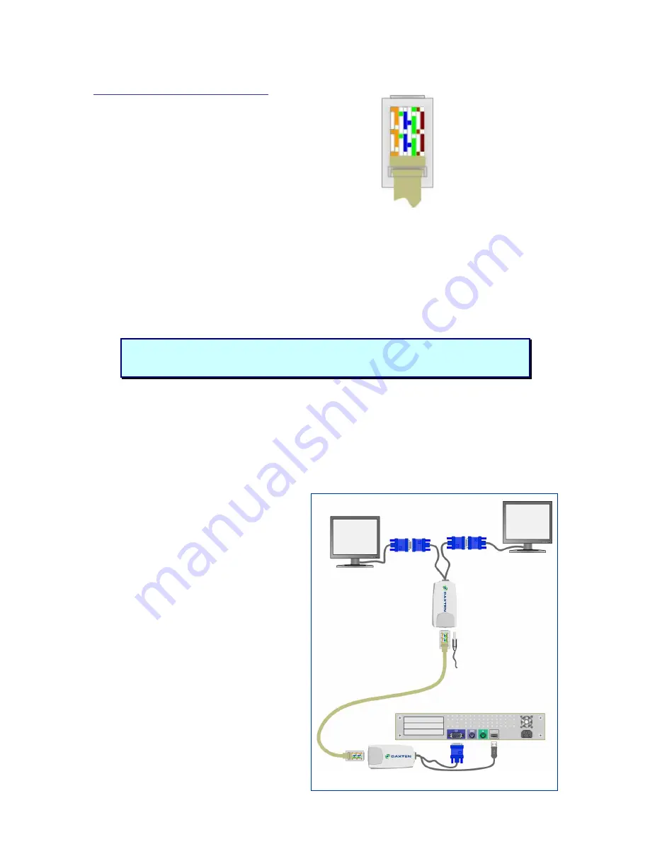
Orientation: Looking into the RJ45 socket pin 1 is on the left and pin 8 on the right.
Pin Wire Colour
Wire Pair
1 White/Orange T2 2
2 Orange/White R2 2
3 White/Green
T3 3
4 Blue/White
R1 1
5 White/Blue
T1 1
6 Green/White
R3 3
7 White/Brown
T4 4
8 Brown/White
R4 4
Connecting up without a DisplayIt Micro Splitter
1.
Switch off your computer.
2.
Connect the DisplayIt Micro Transmitter unit to your computer’s monitor port. Connect the
USB power adaptor into your computers USB port.
3.
Connect your UTP cable to the DisplayIt Micro’s Transmitter and Receiver units.
4.
Connect the DisplayIt Receiver to your remote monitor
5.
Connect the power supply unit to the DisplayIt Receiver unit.
6.
Adjust the picture tuner with the screwdriver on the DisplayIt Micro Receiver unit if required.
Note:
When using a DisplayIt micro Splitter, the Splitter will supply power over the UTP
cable to the DisplayIt micro receivers.
Do not connect the cable to any other device.
Connecting up with a DisplayIt Micro Splitter
1.
Switch off your computer.
2.
Connect the DisplayIt Micro Transmitter unit to your computer’s monitor port. Connect the
USB power adaptor into your computers USB port.
3.
Connect your UTP cable to the DisplayIt micro Splitter.
4.
Connect the DisplayIt Micro Receivers with the remote monitors and the micro Splitters.
5.
Adjust the picture tuner with the screwdriver on the DisplayIt Micro Receiver unit if required.
Quick Setup Guide
You can daisy chain the Micro Splitter by
connecting a UTP cable to the RJ45 out and
the RJ45 in port on another Micro Splitter
Unit.
Place cables away from fluorescent lights, air
conditioners, and machines that are likely to
generate electrical noise
LED indicators
The DisplayIt Micro Transmitter and Receiver
units both have 2 LEDs above the RJ45 port.
The green LED indicates power is on. The
flashing yellow LED indicates the system is
connected.


