27
28
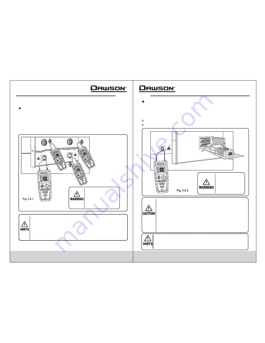
3.2.2 Find correct breaker
Connect the transmitter to a socket connected to the
breaker panel under test and adjust the transmitter
power to a suitable level.
Turn off all switches at the breaker box
Connect the transmitter to the test socket as in fig. 3-2-2
Please observe
standard safety
precautions when
connecting the
transmitter to a
charged circuit.
1. Correctly identifying proper breakers is greatly
influenced by the wiring of the breaker box. In order to
more precisely find the correct breaker, one can remove
the cover from the breaker panel and search for the
feeder line to the breaker.
2. During the identifying process, the breaker with the
strongest and most stable signal will be the target
breaker. Due to potential coupling of signals, the
receiver may detect signals in other breakers, but the
strength of those signals will be relatively weaker.
1. During detection, it's best to put the tip of the receiver
directly into the fuse box to achieve the best results.
2. Adjust the transmitter power to get an adequate signal
depending on the detection environment.
3.2.1 Closed circuits
For use on charged or uncharged circuits
For uncharged circuits, the transmitter only sends signals
to be received by the receiver.For charged circuits, the
transmitter not only sends signals for the receiver, but
also measures the voltage of the connected circuit.
Please observe
standard safety
precautions when
connecting the
transmitter
to a charged circuit.
1. The maximum input voltage of the transmitter is 400V AC/DC
2. The closed circuit application works for detecting
connected sockets, switches, fuses, etc.
3. Detection depth depends on the type of circuit, cable, usage
of cable/circuit, etc. Normal operating depth is <0.5m.
4. Adjust the transmitter power to get an adequate signal
depending on the detection environment.
3.2 Dual-pole Applications


