background image

6

GPS/Wireless System Wiring Diagram

Note: If installing the GPS/Wireless System with a DriveRight 600, use an #8157 GPS Module 

instead of the #8128 GPS Module and connect it to the GPS Wireless Interface Module 
as shown on the previous page. Make sure to plug part #07381.129 (sold separately) into 
the connector labeled “GPS” on the GPS/Wireless Interface Module. If connecting the 
GPS/Wireless System to a DriveRight 600 without a GPS Module present, the plug is not 
needed as part of the installation. Contact Davis instruments or your local retailer or 
distributor for details. See “Contacting Davis Technical Support” on page 14 for more 
information.

Making Connections

The GPS/Wireless Interface Module can be installed with either the GPS 
Module, the Wireless On-Board Module or both. The instructions below 
assume an installation involving all three modules. Modify your own 
installation as necessary.

1. Connect the GPS Module to the GPS/Wireless Interface Module by 

plugging the male connector of the GPS Module cable into the socket 
labeled “GPS” on the GPS/Wireless Interface Module.

2. Connect the Wireless On-Board Module to the GPS/Wireless Interface 

Module by plugging the male connector on the Wireless On-Board Module 
cable into the socket labeled “W” on the GPS/Wireless Interface Module.

3. Disconnect the DriveRight 600

E

, or 600 device or optional SmartCard On-

Board Reader cable from the Digital Input Adapter Cable or optional #8157 
GPS Module.

4. Connect the male connector from the GPS/Wireless Interface Module cable 

to the female connector on the Digital Adapter Cable or optional #8157 
GPS Module.

5. Connect the female connector on the GPS/Wireless Interface Module to the 

male connector on the DriveRight 600

E

, 600, or optional SmartCard On-

Board Reader cable.

Summary of Contents for DriveRight 8127

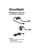
Page 1: ...Includes GPS Wireless Interface Module 8127 GPS Module 8128 Wireless On Board Module 8129 GPS Wireless System Installation Manual...

Page 2: ...the FCC Rules These limits are designed to provide reasonable protection against harmful interference in a residential installa tion This equipment generates uses and can radiate radio frequency ener...

Page 3: ...Fleet Management Software for your fleet before installation in a vehicle See the FMS Online Help System for information configuring both of these modules Some components of the GPS Wireless System m...

Page 4: ...with GPS Wireless Interface Module 8127 and can be used with all three components The GPS Wireless Interface Module 8127 should come with the mounting hardware above and the component shown below Vel...

Page 5: ...ware The GPS Module 8128 is sold separately and comes with the component shown below The Wireless On Board Module 8129 is also sold separately and comes with the component shown below GPS Module 8128...

Page 6: ...GPS Wireless Interface Module GPS Module and Wireless On Board Module to an existing DriveRight 600 or 600E system Wiring the GPS Wireless System with a DriveRight 600E W GPS SmartCard On Board Reader...

Page 7: ...W GPS SmartCard On Board Reader 8104 or 8105 optional DriveRight 600 8156 Wireless On Board Module 8129 GPS Wireless Interface Module 8127 Digital Adapter Cable 07381 129 sold separately Required if...

Page 8: ...e instructions below assume an installation involving all three modules Modify your own installation as necessary 1 Connect the GPS Module to the GPS Wireless Interface Module by plugging the male con...

Page 9: ...Cables Hold both cables by their connector housing and pull apart The housing of the male connector slides to separate the cables Connecting Cables Slide Connector Housing Hold the female connector an...

Page 10: ...e same location as the 8128 GPS Module shown in the drawing above 1 Place the GPS Wireless Interface Module under the dashboard of the vehicle near the DriveRight 600E device or SmartCard On Board Rea...

Page 11: ...reless Interface Module and plug the connector into the correct socket 6 Mount the Wireless On Board Module on a corner of a windshield Special requirements that should be taken into account when moun...

Page 12: ...lot this module communicates with a Base Station for Wireless Download System 8130 and moves the DriveRight data to the FMS database Base Station for Wireless Download System 8130 The Base Station fo...

Page 13: ...f a sample Wireless Download System network USB Port Configuration Cable for Wireless On Board Module 8131 Base Station for Wireless Download System 8130 8129s installed in your fleet communicate with...

Page 14: ...m For the GPS Module 8128 Size 2 38 x 2 38 x 1 00 58 mm x 48 mm x 27 mm Weight 4 0 oz 0 113 kg Operating Range 40 F to 176 F 40 C to 80 C Storage Range 40 F to 194 F 40 C to 90 C Input Power 5Vdc Typi...

Page 15: ...torage Range 40 F to 194 F 40 C to 90 C Input Power 3 3V Typical Standby Current 10mA Typical Transmit Current 270mA Cable Length 96 2 4 m Connector 7 pin locking Mini DIN Wireless Transmitter Specifi...

Page 16: ...t Note Please do not return items to the factory for repair without prior authorization Phone Support 510 732 7814 Monday Friday 7 00 a m 5 30 p m Pacific Time 510 670 0589 Fax to Technical Support E...

Reviews: