background image

21 


1.


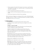
Place your gateway in the center of the network. For most devices, every time data is 
transmitted over one repeater hop, it loses half its speed. A central gateway minimizes 
the number of hops required.


2.


Never go through more than three to four walls or floors.


3.


Never go more than 50-150 feet (depending on building materials) between access 
points.


4.


Install no more than about five repeaters to every one gateway.


Once all access points are plugged in, you should see them turn green on the Network Manager 

Status page in about 5 to 15 minutes. For more detailed information on planning and optimizing 
your network, see the 

Network Planning Guide

.


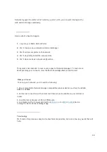
7.


Configuring A Network 

Your network should now be up and running, but there’s a lot we can do to 

customize it to meet your specific needs. We’ll walk you through the most common 
settings here.


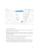
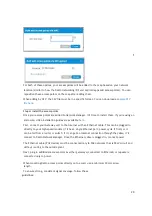
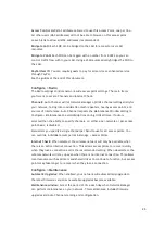
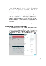
Configure > General Settings


The General Settings tab controls network-wide settings. This will be partially filled 

in with the information you used to create the network.


Location: This defaults to the first address you entered when setting up the 

network. You can change it at any time. Note that the location only determines 
where your access point appears on the map; radio settings will be based on the IP 
address of the access point.


Network name: The login name for this network on the dashboard, and also the 

login ID to access this network individually by a site administrator. This is NOT your 
master login. This allows you to give access to only the network settings for that 
network without allowing access to your master account.


Time Zone: Used in displaying the local time on reports.


AM/PM time: Used in displaying the local time on reports.


Display Name: Used to display a more descriptive name (other than the login ID) on 

reports. Password: The administrator password for this network. Again, this is only 
for this network and is not your master login password. It is also not the password 
your users will use to connect to the network.


Summary of Contents for AP440

Page 1: ...1 User Guide Datto AP440 Version 1 2 July 30 2021 ...

Page 2: ...t to an Ethernet Junction Box 9 5 4 How to Mount to a Flat Surface Wall or Ceiling 10 5 5 How to Mount to a Pole 11 5 6 How to Mount to T Rails 12 6 Creating a Network on Network Manager 13 7 Configuring a network 21 8 Configuring Device for Indoor or Outdoor Use 27 9 Monitoring Management and Troubleshooting 28 10 Additional Resources 29 11 Appendix A FCC Statement 30 12 Appendix B IC Statement 3...

Page 3: ... de réparation ou de démontage WARNING 24V Passive PoE is not supported on this device do not attempt to use Damage can result AVERTISSEMENT le PoE passif 24 V n est pas pris en charge sur cet appareil n essayez pas de l utiliser des dommages peuvent en résulter Restriction Statement The 5150 5350 MHz band is allocated for indoor use only in EU member countries and Canada BE BG CZ DK DE EE IE EL E...

Page 4: ...02 11a b g n ac ax Processor Quad Core CPU 1 8GHz Memory 1GB DDR3 Ethernet Ports 2x 10 100 1000 Mbps RJ45 Ethernet Ports PoE 1x 802 3AF AT Standard PoE input DC Power Input 12V 2 5A DC Power input USB 1x USB 2 0 Operating Temperature 20C 50C Installation Environment Indoor or Outdoor Installation LEDs Tri Color LED Status Indicator Hardware CPU Watchdog Yes Size 7 3 x 7 3 x 1 6 186mm x 186mm x 40m...

Page 5: ...5 3 Product Overview 4 Included Accessories ...

Page 6: ...6 Drywall Screw Dimensions Drywall Anchor Dimensions ...

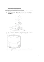
Page 7: ...et around the Ethernet cable align with the I O coverspacing and push gasket into place 3 Place the I O port cover in place over the Gasket and leveraging theprovided Allen and Torque tool screw the 5 Hex screws into place 4 Once Done you will want to use the plugs and fill the unused I OHoles 5 For Best Sealing and protection of Product do not mount the device with the Ethernet cables facing upwa...

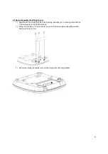
Page 8: ...ide of the Housing and align the 3 mounting holes with the 3 screw mounts on the AP440 Housing 2 Using the Provided I O Cover screws screw the 3 screws in place using theprovided Allen and Torque L Tool 3 Now when routing the cables route up and through the Mounting bracket ...

Page 9: ... the mounting plate to the JunctionBox 2 Connect the Ethernet Cable to the Access Point Ethernet Port with 802 3AF AT PoE input 3 Alternatively you can supply power to the device using the 12V DC Powerinput 4 Install the Access Point on the mounting plate and lock intoplace ...

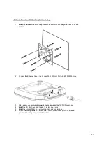
Page 10: ... the Access Point Ethernet Port with 802 3AT PoEinput 3 Alternatively you can supply power to the device using the 12V DC Power input 4 Install the I O Port Cover and Gasket if installed outdoors 5 Install the Access Point on the mounting plate and lock intoplace 6 Attach Grounding Cable to the Grounding Point on the Access point and screwin provided Grounding screw if installed outdoors ...

Page 11: ...4mm 1 Install Clamp Cabling through the slots on the MountingPlate 2 Connect the Ethernet Cable to the Access Point Ethernet Port with 802 3AF ATPoE input 3 Alternatively you can supply power to the device using the 12V DC Powerinput 4 Install the I O Port Cover and Gasket if installed outdoors 5 Install the Access Point on the mounting plate and lock into place 6 Attach Grounding Cable to the Gro...

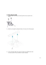
Page 12: ...ing Plate Secure Clips with T Rail Screws 2 Install the mounting plate by pressing both clips on the ceiling T rail until fully engaged 3 Connect the Ethernet Cable to the Access Point Ethernet Port with 802 3AF AT PoE input and assemble I O Cover and Gasket for outdoorinstallations ...

Page 13: ...e is intended to help you set up your first cloud managed wireless mesh network with Datto Network Manager Network Manager is a cloud based network controller that makes it easy for anyone to build manage and monitor wireless networks from anywhere in the world This guide will assist you in setting up a new network on the Datto Network Manager web application For easier faster setup use the Datto ...

Page 14: ... Manager To learn more about planning your network view the Datto Knowledge Base kb datto com What you ll need To set up your network you ll need the following 1 One or more Datto Network Manager compatible wireless devices such as the AP440 AP840 or AP840E 2 An Internet connection with at least one Ethernet port available on your modem or router 3 one Ethernet cable and a 802 3at POE source 4 A c...

Page 15: ...puters and other access points to the gateway Access point A generic name for an Network Manager compatible router access point which can be either a Gateway or a Repeater You may also see these called Nodes All Datto Networking Access Points configure themselves they become gateways or repeaters depending on if they are connected to the Internet or not Step 1 Log into the Datto Partner Portal dat...

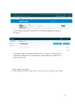
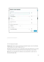
Page 16: ... may create new network to add this device to or navigate to the network you would like to add this device to For this guide we will be setting up a new Network So click Create Network Step 2 Create a new network You ll automatically be taken to a page similar to the one below to create your first network ...

Page 17: ...nges to the network display reports etc Password This is the password for local administrators and should be different from your master account login This limits access and prevents users from making changes to your network Email Enter your email address or the address of a local administrator to contact We will never share this with others ...

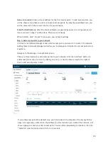
Page 18: ...which access points you want to include in the network Adding them to Network Manager will allow you to manage and monitor the access points from anywhere Navigate to the Manage Access Points screen There are three options to add access points to your network click the Add New button to add access points one at a time by clicking on a map or use the down arrow to the right of that to add access po...

Page 19: ...e router and on the side of the product box Description You can enter optional descriptive text that will be shown on the reports This is typically used to keep notes on where the access point is installed etc Click Add and repeat the process for each additional access point If you need to add a large number of access points you may want to add them in bulk You can do so two ways by entering the M...

Page 20: ...r Gateway unit to the Internet with an Ethernet cable This can be plugged in directly to your high speed modem if it has a single Ethernet port power cycle it first or it can be fed from a router or switch If it can get an Internet connection through the cable it ll connect to Datto Network Manager Once the Ethernet cable is plugged in connect power The Ethernet cable PoE device must be connected ...

Page 21: ... tab controls network wide settings This will be partially filled in with the information you used to create the network Location This defaults to the first address you entered when setting up the network You can change it at any time Note that the location only determines where your access point appears on the map radio settings will be based on the IP address of the access point Network name The...

Page 22: ...d your network we set the first SSID to be public and the second SSID to be private but you can adjust these any way you wish We ll go through most of the features you may want to enable or change You can also learn more about voucher access pay networks and more by following the links at the end of this document Common Settings SSID name The name you d like users to see and connect to with their ...

Page 23: ...dle Idle Timeout before showing splash page or minutes between showing splash page regardless of activity Force Timeout for non voucher access 1 day 1440 Require voucher Require a valid voucher on splash pages If unchecked allows you to provide a basic tier of service at the rates and durations above and optionally faster service using vouchers or PayPal Redirect URL The page to display after the ...

Page 24: ...ul in applications such as VoIP calls that must maintain continuity of connection This option is only available if the SSID has WPA authentication enabled Block LAN Access Prevents users on this wireless network from accessing your wired LAN Client isolation Prevents your wireless users from being able to access each other s computers and common for public networks Unchecking this box will allow y...

Page 25: ...setting in Configure Maintenance to avoid disruptions during critical times If Auto is selected then the ability to specify channels on either a per network or per access point basis is disabled Manual lets you specify a single channel per band to use for all access points You can override individual access points in Manage Access Points Internet Check When selected the wireless network will only ...

Page 26: ...n t change This section will touch on the more common settings AP Mesh When disabled this turns off meshing on your APs Mesh Encryption must be enabled Mesh Encryption Encrypts all mesh traffic with WPA2 protection Access points not belonging to this network won t be able to join the mesh due to the encryption Alternate DNS Alternate DNS server IP address for your network such as OpenDNS OpenDNS p...

Page 27: ...lients access to LAN resources such as file servers and printers disables NAT and lets your LAN assign all client DHCP addresses You can bridge additional SSIDs by using a VLAN tag on each SSID settings page Delete Network Select to delete this network from Network Manager 8 Configuring a Device for Indoor or Outdoor Installation This access point can be configured as an indoor model in addition t...

Page 28: ...shows how all nodes relate to each other STATE COLOR Checkin performed mesh speed 2Mbps Flash Green Orphan mode Flash Yellow then Green Lonely mode Flash Red then Green checkin performed mesh speed 2Mbps Solid Green You can use each of these tools to see how your network is doing and troubleshoot issues Troubleshooting in Datto Network Manager Have you have created a strong healthy network While t...

Page 29: ...ting Up Solid Yellow Firmware upgrade node is executing the firmware upgrade Solid Red Cloud check in failure Flash White Key re pair Flash Yellow Configuration change AP not ready Solid White Net failure no default route Flash Red 10 Additional Resources To learn more about planning and optimizing your network download the Datto Network Planning Guide To learn more about Datto s splash page featu...

Page 30: ...technician for help FCC Radiation Exposure Statement This equipment complies with FCC radiation exposure limits set forth for an uncontrolled environment This equipment should be installed and operated with minimum distance 22 cm between the radiator your body FCC Caution Any changes or modifications not expressly approved by the party responsible for compliance could void the user s authority to ...

Page 31: ...Installation Location The product shall be installed at a location where the radiating antenna can be kept 22 cm away from nearby person in normal operating condition to meet regulatory RF exposure requirements 3 External Antenna Use only the antennas which have been approved by the applicant The non approved antenna s may produce unwanted spurious or excessive RF emissions which may lead to the v...

Page 32: ...ent Caution i the device for operation in the band 5150 5250 MHz is only for indoor use to reduce the potential for harmful interference to co channel mobile satellite systems ii where applicable antenna type s antenna models s and worst case tilt angle s necessary to remain compliant with the e i r p elevation mask requirement set forth in section 6 2 2 3 shall be clearly indicated Avertissement ...

Page 33: ...rsonal who has RF and related rule knowledge The general user shall not attempt to install or change the setting 2 Installation location The product shall be installed at a location where the radiating antenna can be kept 26 cm from nearby person in normal operation condition to meet regulatory RF exposure requirement 3 External antenna Use only the antennas which have been approved by the applica...

Page 34: ...e produit doit etre installe de facon a respecter une distance de 26 cm entre l antenne emettrice et les personnes 3 Antenn externe Utiliser uniiquement les antennes approuvees par le fabricant L utilisation d autres antennes peut conduire a un niveau de rayonnement essentiel ou non essentiel depassant les niveaux limites definis par ISED ce qui est interdit 4 Procedure d installation Consulter le...

Page 35: ...ntenna during body worn operation to comply with the RF exposure requirements in Europe The following Test methods have been applied in order to prove conformity with the essential requirements of the EU Directive 2014 53 EU Radio EN 300 328 EN 301 893 RF Exposure EN 50385 EN 62311 EMC EN 301 489 1 EN 301 489 17 Emissions EN 55024 EN 55032 EN 55035 Safety EN 62368 1 EN 60950 22 IEC 60529 14 Append...

Page 36: ... 53 ΕU Français French Par la présente Datto déclare que ce point d accès sans fil AP440 est conforme aux exigences essentielles et aux autres dispositions pertinentes de la directive 2014 53 EU Italiano Italian Con la presente Datto dichiara che questo Access Point wireless AP440 è conforme ai requisiti essenziali e ad altre disposizioni pertinenti della Direttiva 2014 53 EU Latviski Latvian Ar š...

Page 37: ...a dostopna točka AP440 v skladu z bistvenimi zahtevami in drugimi ustreznimi določbami Direktive 2014 53 EU Slovensky Slovak Týmto spoločnosť Datto vyhlasuje že tento bezdrôtový prístupový bod AP440 je v súlade so základnými požiadavkami a ďalšími príslušnými ustanoveniami smernice 2014 53 EÚ Suomi Finnish Täten Datto vakuuttaa että tämä langaton tukiasema AP440 on direktiivin 2014 53 EU olennaist...

Reviews: