background image


https://www.datavideo.com/product/WM-10


May-21.2021    Ver:E2 

Datavideo Technologies Co., Ltd. All rights reserved 2020 


Summary of Contents for VM-11

Page 1: ...WM 10...

Page 2: ...information However Datavideo Technologies cannot exclude that some information in this manual from time to time may not be correct or may be incomplete This manual may contain typing errors omission...

Page 3: ...rranty from the date of purchase Damage caused by accident misuse unauthorized repairs sand grit or water is not covered under warranty Viruses and malware infections on the computer systems are not c...

Page 4: ...r household waste Instead it is your responsibility to dispose of your waste equipment by handing it over to a designated collection point for the recycling of waste electrical and electronic equipmen...

Page 5: ...to a 100 kg load Note WM 10 is designed for PTR series of robotic pan tilt heads and PTC series of PTZ cameras Parts Assembly and Installation In this section you will be shown how you can assemble an...

Page 6: ...the surface where the WM 10 is to be mounted drill four holes spaced according to the dimensions indicated in the diagram below Then follow the procedure in the next section to assemble and install th...

Page 7: ...7 Procedure The diagram below is an exploded view drawing of WM 10 and the numbers correspond to the respective installation steps 1 2 3 4 5 Bubble Level Meter...

Page 8: ...four holes drilled in Pre Work then use four expansion bolts to secure the wall plate See the diagram below 2 Assemble the left bracket to the wall plate with two M5x20 nickel plated hex socket cap sc...

Page 9: ...ated hex socket cap screws as shown in the diagram below 4 Place the round rod in between the left and right brackets then secure it in position by fastening two M5x20 nickel plated hex socket cap scr...

Page 10: ...as shown in the diagram below The inner rails on the right and left brackets should allow you to move the base plate back and forth Please note that you can use the bubble level meter to check if the...

Page 11: ...place it on the base plate of the WM 10 such that the four screw holes at the bottom of the PTR 10 10T base are aligned with the screw holes found in the base plate as indicated in the diagram below S...

Page 12: ...12 If after installation the PTR 10 10T vibrates you may enhance the installation by securing the base with four M3 x 8mm screws The additional screw holes are depicted in the diagram below...

Page 13: ...ndard accessories of PTC 150 Ceiling bracket M4 screw x 4 WM 10 wall mount To mount the PTC 150 on the WM 10 use four M4 screws to secure each of the upper and lower plates of the ceiling bracket to t...

Page 14: ...14 The WM 10 with the PTC 150 mounted is shown in the diagram below...

Page 15: ...olutions If problem still exists please contact your distributor or the service center No Problems Solutions 1 PTR 10 10T vibrates after installation If after installation the PTR 10 10T vibrates you...

Page 16: ...16 Dimensions and Weight Unit mm Weight 4 0 Kg 8 80 lb Maximum load 100 Kg...

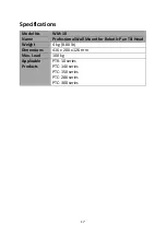
Page 17: ...No WM 10 Name Professional Wall Mount for Robotic Pan Tilt Head Weight 4 kg 8 80 lb Dimensions 416 x 200 x 126 mm Max Load 100 kg Applicable Products PTR 10 series PTC 140 series PTC 150 series PTC 28...

Page 18: ...18 Notes...

Page 19: ...19 Notes...

Page 20: ...https www datavideo com product WM 10 May 21 2021 Ver E2 Datavideo Technologies Co Ltd All rights reserved 2020...

Reviews: