background image

33


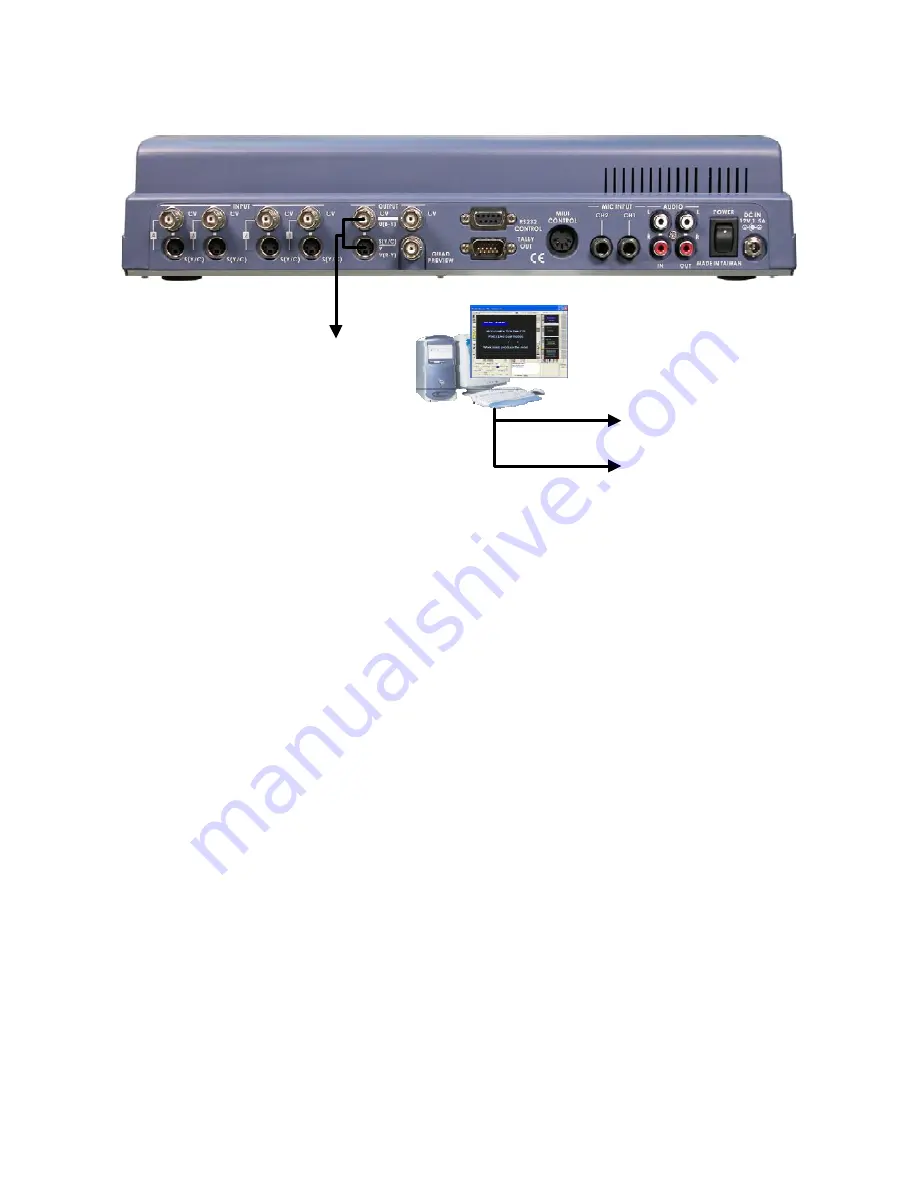
Using SE-500 with CG-100 for Titles/Graphics/Logos overlay


Connect to DecklinkSP 

YUV input on a PC with 

CG-100 installed 

To Master Recorder 

Deck 

To Projector 

Or 

Using YUV output (with a breakout cable) on SE-500 to communicate with a PC with Decklink SP CG 
overlay card and CG-100 CG software

 ø°¿¹» ìî÷ 

to perform a text overlay for the output video.

Summary of Contents for SE-500

Page 1: ...Ü Ê Í ÍÛóëðð Û ÿ ÒÍÌÎËÝÌ ÑÒ ÓßÒËßÔ Ø æññ ò ª ó µò Rev 300606 ...

Page 2: ...Quick Start 9 Front panel 9 Rear panel 13 Selecting video input formats and adjusting audio levels 16 Selecting video output format 16 Using Video and Audio Monitors 16 Cutting between sources 16 Dissolving between sources 17 Other Transitions between sources 17 Effects 17 Controls and Operations 19 Video Source 19 Color Processor 20 Menu 20 Audio Inputs Levels and Meters 22 Using Transitions 23 S...

Page 3: ...age at output S Video output is black and white 34 Audio clipping 34 Frozen image at output 34 Image distortions etc 34 How does RS 232 work in practice 34 Appendix 35 Glossary of terms 35 Tech notes Video Standards Formats and Quality Monitor Calibration 37 Specifications 40 Useful Accessories 42 RS 232 Remote Control Commands 45 MIDI Control Commands 50 Tally Pinouts cross reference between the ...

Page 4: ... service this product yourself Opening or removing covers that are marked Do Not Remove may expose you to dangerous voltage points or other risks and will void your warranty Refer all service issues to qualified service personnel 13 Unplug this product from the wall outlet and refer to qualified service personnel under the following conditions a When the power cord is damaged or frayed b When liqu...

Page 5: ...other than that specified by Datavideo or has been subjected to abuse or modification will be repaired for time and material charges at the Buyer s expense This warranty does not affect your statutory rights within the Country of purchase For EU Customers only WEEE Marking This symbol on the product indicates that it will not be treated as household waste It must be handed over to the applicable t...

Page 6: ... video input sources camera activities and video transition effects The SE 500 has all the popular features of many more expensive mixers and it is extremely compact in size Now you can shoot mix and edit all within this compact size digital switcher With the Datavideo DAC 6 DV to Composite Y C and Component converter VP 314 DV Repeater and 10 20 40meter DV cables you may use DV cameras to feed vi...

Page 7: ...ppen eventually Have a continuity tester handy and save yourself some troubleshooting headaches Make sure you don t run video audio cables and power lines together on top of each other or across each other This is another good way to introduce noise and signal degradation Cable connectors will eventually become dirty or oxidation will start The dirt can cause a bad connection or introduce noise in...

Page 8: ...phono plugs cinch or tulips are used for line level audio such as the connections between a CD player and amp The SE 500 uses these in stereo pairs white for left and red for right at the audio input and output sections 1 4 inch jack plugs got their name some say because they used to be used to manually patch together phone lines in the old central switchboard days They come in mono and stereo con...

Page 9: ...a Needless to say if you are outputting to a record deck you should be able to easily monitor the output of that device as well Audio Mixer An Audio Mixer with two mono microphone inputs and stereo Aux input allows you to adjust and balance the volume from various audio sources RS 232 control The RS 232 Control Port enables control of the SE 500 from a PC or other device thru the RS 232 port Conne...

Page 10: ...tion Effect preview 13 Main Video Source selectors 14 Sub Video Source selectors 15 Transition mode selectors 1 Audio faders 2 Headphone Socket 3 Audio meters 4 Headphone Volume Control 5 Video Effect Quad 6 Video Effect Split 7 Video Effect PIP 8 Video Effect Freeze 1 2 3 4 5 6 11 7 8 9 15 10 12 14 13 ...

Page 11: ...hone level and signal s present at the Headphone jack 2 Level is controlled by the rotary knob For more information see Using Video and Audio Monitors ïê and Audio Inputs Levels and Meters îî 5 Quad Video Effect combines four different input sources into one single output on program monitor 6 Split Video Effect split the selected Sub Video Source and the Main Video Source into left and right half ...

Page 12: ...output 11 Border controls the border style and color for the Picture in Picture effect and the color edge for the Wipe effect This control is accessible when the Picture in Picture controls and Wipe transitions 15 are engaged For more information see Using Effects Picture in Picture îé and Using Transitions Wipe îíò 12 T Bar used to manually perform a transition For more information see Playing a ...

Page 13: ... changing video from one format to another for example from composite video to S video The SE 500 has been designed to perform transcoding as part of its standard operating procedure Select a video source on the Main Source Input bus and it will be available at the Main Output in all formats S Video and Composite simultaneously N B The output format can be S Video and Composite or Component Video ...

Page 14: ...connector 9 Two Stereo Audio outputs RCA 10 Power On Off switch 11 DC Power input 12V 1 5A 3 6 4 5 1a 1b 2a 2b 2c 2d 7 8 9 11 10 1 Video inputs Channels 1 2 3 4 1a S Video Y C input 1b Composite video input BNC 2 Video outputs 2a Composite video out BNC 2b S video Y C out 2c Component Combine Composite Y C with supplied breakout cable 2d Quad preview output BNC ...

Page 15: ...o a device d Quad preview out BNC connector carrying a quad video signal with effect Tally light background and speed indicators 3 RS 232 control for PC or other devices to remote control via RS 232 protocol Please read the Appendix of RS 232 Protocol on ìë for more information 4 Tally Out send out Red Amber and Green color tally signals to each channel Red means On Air Amber means next camera sou...

Page 16: ...alanced Audio input 9 Audio Output A RCA stereo line level analog audio output carrying the signal present at the output of the audio mixer section see Controls and Operations ïç 10 Power Switches the unit On Off 11 DC Input connect the power supply that came with the SE 500 and only the power supply that came with the SE 500 here and plug the other end into an electrical outlet preferably on a su...

Page 17: ...and hold the Background Button for 5 Seconds until the On Screen Menu appears Press the Background Button again and the second page of the menu will appear Use the UP and Down Buttons to navigate the menu and highlight Video Output Video Output can be set to Y C C C or Y U V C If you want to output S Video use the Left or Right Arrow Buttons to select Y C C C If you want to use Y U V Component Out...

Page 18: ... press it At this point you can hit Preview 12 to see the transition on the preview monitor Then use the T Bar to perform the transition manually For more information see Using Transitions îí Effects There are two places on the SE 500 where you can add effects in the Transition Effects section 15 and in the Video Effects section 5 8 Some of these work on a single source and some need two or four s...

Page 19: ... monitor you will have Channel 1 as the Main Source and Channel 2 as a smaller window inset There are two choices for window size Change these by pressing the and buttons see below You can position this window using the other five different position buttons on 15 with the button set to Position Control LED is lit You could also add a border by turning on the Border control 10 Next try the Freeze e...

Page 20: ...ut select if there is an S Video cable connected to the S Video input the channel will automatically switch to S Video input However this means that if both composite and S Video inputs are connected and there is no valid video signal present thru S Video you will see a black video when that channel is selected for output For example if you have a camcorder connected to channel 1 through the compo...

Page 21: ...ontrols the saturation or intensity of the color image from fully saturated or extremely intense at the top of the scale to completely de saturated or monochrome black and white at the bottom The Tint buttons NTSC only control the actual hue or specific colors in the image in effect rotating all the colors equally around an imaginary color wheel Reset works on the selected input source and when pr...

Page 22: ...gs remain in effect until they are changed or the Reset button is pressed MENU The MENU works when you press and hold the BACKGROUND 9 button for 2 seconds or more which is temporarily displayed at the Preview Output The first adjustment is the Color Processor as described above Press the button again and you can select IRE video output format remote control protocol and color bar output Use the u...

Page 23: ...s well as the master output level When the faders are set to 0 they pass the audio signal through at the same level it was at when it entered this bus You can increase or decrease the volume of each channel by moving the fader up or down These meters show the audio signal level at the Main output The strength of any audio signal that is routed to the output will be displayed here As mentioned abov...

Page 24: ...lled back or pushed on to the other But a picture is worth a thousand words so Select a main source and sub source select Wipe or Fade from the buttons above press Preview button to see what it would like on program Then perform the actual transition manually by moving the T bar up and down See below for a list of transitions and variations Playing a transition The T Bar is the traditional switche...

Page 25: ...nter to full screen 2 Right angle wipe on upper right to lower left 3 Right angle reveal lower right to upper left 4 Right angle wipe on upper left to lower right 5 Right angle reveal lower left to upper right 6 Horizontal wipe top to bottom 7 Horizontal wipe bottom to top 8 Vertical wipe left to right 9 Vertical wipe right to left ...

Page 26: ...25 10 Vertical wipe middle to left and right 11 Horizontal wipe middle to top and bottom ...

Page 27: ...he source video return to full motion With the Freeze effect there are no parameters just a single source stopping and starting For more information on single channel effects see the appropriate section Freeze below Dual channel effects are produced on the source selected in the Main Video Source bus and require a second source which is always selected in the Sub Video Source bus Dual channel effe...

Page 28: ... Picture in Picture effect puts the selected Sub Video Source in a window on the Main Video Source Variables for this effect include window size and position Engage the effect by pressing the Picture in Picture button and verifying that the LED on the button is lit Window size 2 sizes are available change the window size by pressing the and buttons on the left of the Wipe transitions is larger is ...

Page 29: ...and we thought you d look here for any information you might need These controls select what solid color the background will be when selected on either the Main or Sub Video bus There are eight possible background colors see below the LED lights up in the selected color except for black where the LED goes out and it is indicated on the preview monitor output The background colors are black blue ma...

Page 30: ...examples is meant to illustrate a typical type of use for the SE 500 Needless to say there will be many variations on any of these themes Try to look for the principles of each set up and adapt these to your particular situation As you get deeper into working with your SE 500 in different situations you should familiarize yourself with the Tech Notes íéô Accessories sections ìî and Appendix íë for...

Page 31: ... the camera operators will be aware when they are live or save to re position Depending on the complexity of the shoot you may want to use an external Mic Audio Mixer to handle the audio and then channel the output of the audio mixer to the SE 500 or simply use the two Mic inputs and have an audio source such as a CD player for background music If you shooting a sporting event the main microphone ...

Page 32: ...aptop of a PowerPoint presentation that the speaker will be referencing throughout his speech There is a microphone feed from centre stage and the possibility of a second microphone for ambient sound or perhaps to field questions from the audience The output can be fed to a giant screen video wall or projector the audio output can be fed to the P A System In this situation the vision mixer operato...

Page 33: ... animated patterns or backgrounds promotional videos music videos just about anything The audio from one of the DVD decks is being fed into the aux audio input although it is more likely you would run both the DVD player audio feeds into an external audio mixer together with CD players keyboards and other audio feeds The mixed output from the audio mixer would then be fed into the SE 500 The job o...

Page 34: ... DecklinkSP YUV input on a PC with CG 100 installed To Master Recorder Deck To Projector Or Using YUV output with a breakout cable on SE 500 to communicate with a PC with Decklink SP CG overlay card and CG 100 CG software ø ìî to perform a text overlay for the output video ...

Page 35: ... Screen Menu appears Press the Background Button again and the second page of the menu will appear Use the UP and Down Buttons to navigate the menu and highlight Video Output Video Output can be set to Y C C C or Y U V C If you want to output S Video use the Left or Right Arrow Buttons to select Y C C C If you want to use Y U V Component Output via the supplied Breakout Cable then select Y U V C A...

Page 36: ...g redundant information then reconstructing the data to its original form can be either lossless or lossy Color correction the use of filters processing amplifiers and other software and or hardware devices to correct a video image dB a unit of measurement for audio signal levels Digital video a method of representing still or moving images by number values instead of by varying magnetic levels an...

Page 37: ...lution a measure of the detail in an image or a sound Image resolution is often described in pixels i e 1024 x 768 pixels or bit depth i e 8 or 10 bit Sound resolution is described in terms of sampling frequency kHz and bit depth The higher the numbers the greater the possible detail RGB one format of component video one of the descriptions of component color space in this case Red Green Blue See ...

Page 38: ...unless the equipment is specifically designed to be multi standard Within each standard are multiple formats different systems of recording video onto different types of medium At the lowest quality and cost level is VHS a composite form of video meaning the chroma color and luma lightness bits of information are electronically mashed together into one signal convenient inexpensive and very much o...

Page 39: ...bars if you don t have them do an Internet search for color bars and take your pick The following procedure will be described using SMPTE bars but EBU bars will work for most of this technique as well As you will see they bars are different in format in part because of the differences in broadcast systems between NTSC and PAL but much of the usage will be the same You can use the SMPTE bars regard...

Page 40: ...information you need But if you don t have a waveform monitor vector scope to adjust incoming video you can make those adjustments by eye using the SE 500 s color processing controls now that you have a properly calibrated program monitor The process for each input channel will be very similar to the process we just used to calibrate the program monitor except we were adjusting the controls on the...

Page 41: ... Output 1 Stereo main outputs RCA connector 1 Stereo headphone Mini jack with volume control 0 3Wrms 8 ohm Quad Channel Time Base Correction Full Frame Synchronization 4 2 2 13 5MHz Digital Effects including A B dissolves PIP border lines and over 12 Wipes with various manually transition speeds RS 232 Data Control Port Connecting PC RS 232 for remote control Color Processing Brightness 10 Y gain ...

Page 42: ...41 Audio 20 to 20KHz 1dB Audio THD 0 1 Dimensions W x D x H 15 75 x 10 5 x 3 25 Approx 400mm x 265mm x 83mm Approx Weight 13 8 lb 5 5 Kg Power Input DC 12V 1 5A ...

Page 43: ...ith the SE 500 SE 800 to give superb quality graphics text logo overlay on live production mixes Datavideo VGA to DV converter PPT 100 In many conferences and seminars lecturers need to present videos and additional PC information to the audience When they switch sources between PC and other medias on the projector will cause the transient black picture and then interrupt the meeting process The s...

Page 44: ...r With contrast brightness color and tint Tint only available for NTSC controls for a best view quality of display Datavideo DAC 6 DV to Analog One way converter The DAC 6 is designed to allow DV cameras to be used with the SE 500 It is a stand alone converter that takes a DV signal in and converts it to an analog output in Composite S Y C or Component format It is a very compact converter and can...

Page 45: ...0K ohms 0K ohm GAIN 4 to 20dB 20dB to 18dB OUTPUT LEVEL 0 to 8dBm nom 22dBm max 10dBv nom 20dBv max OUTPUT LOAD 600 ohms or higher balanced 600 ohms or higher unbalanced FREQ RESPONSE DC to 25kHz 0 5dB DC to 25kHz 0 5dB NOISE LEVEL 80dB below nom output level 80dB below nom output level DISTORTION 0 01 at any frequency 0 01 at any frequency POWER INPUT DC 12V 200mA DIMENSION 140 W x 112 D x 40 H m...

Page 46: ...llow 1st F0h base 16 The return header byte is fixed as fallow 1st FCh base 16 2 ID number The equipment ID number is composed of 8 bits The ID of SE500 32h base 16 3 Length The length is the sum of bytes from the header to the end It is composed of 8 bits 6h base 16 Length 80h base 16 4 Data Data block used by application layer Refer to Section 3 5 Checksum The 8 bits checksum is obtain from head...

Page 47: ...trol 4 1 OP 1 control key code refer to section 5 when OP 0 01H 00h disable remote control T bar when OP 0 02H 01h enable remote control T bar when OP 0 02H 4 2 OP 2 and OP 3 T BAR control value when OP 0 02H The T bar control value is 10 bits The bit4 to bit 0 of OP 1 the low 5 bits of the T bar control value The bit4 to bit 0 of OP 2 the high5 bits of the T bar control value 5 The SE500 control ...

Page 48: ...500 control command status 5th 6 th 7 th 8th 9th 10th 11th 12th parameter 0 parameter 1 Parameter 2 parameter 3 parameter 4 parameter 5 parameter 6 Parameter 7 Error code Busy flag Effect Mode Speed Effect No Background Color border LED1 LED2 LED3 13th 14th parameter 8 parameter 9 LED4 LED5 1 The error code 01h Time out over 15ms 02h length error 03h checksum error 04h not support command 05h oper...

Page 49: ...y_take Bit0 of LED2 LED of key_sub_a Bit1 of LED2 LED of key_sub_b Bit2 of LED2 LED of key_sub_c Bit3 of LED2 LED of key_sub_d Bit4 of LED2 LED of key_sub_bk Bit6 of LED2 LED of key_preview Bit0 of LED3 LED of key_FADE Bit1 of LED3 LED of key_QUAD Bit2 of LED3 LED of key_POP Bit3 of LED3 LED of key_PIP Bit4 of LED3 LED of key_freeze Bit5 of LED3 LED of key_border Bit6 of LED3 LED of key_MENU Bit0 ...

Page 50: ...m_high 04h 30h 34h END ffh b SE500 return data The return data stream Fch 32h 11h 05h 00h 01h 10h 00h 07h 41h 42h 01h 00h 20h 30h 30h ffh Header fch ID 32h Length 17 bytes 11h Command status 05h Error code 00h Busy flag 01h Effect mode speed fade speed_2 00h 10h 10h Effect No 00h Background color border white border off 07h 00h 07h LED1 41h LED2 42h LED3 01h LED4 00h LED5 20h Checksum fch 32h 11h ...

Page 51: ...ed 2 2 Control messages Note on Status 2 nd byte 3 rd byte 9nH kkH vvH Symbol Meaning Range n MIDI channel 0H FH ch 1 ch 16 kk Note number 00H 7FH 0 127 SE500 control command vv Velocity value etc 00H 7FH 0 127 Only in the case of Note on Velocity 01H 7FH 1 127 3 SE500 control command correspond to note number as follows Note Note No SE500 command C4 48 fade key C 4 49 wipe key D4 50 wipe key D 4 ...

Page 52: ... key F6 77 MAIN D key F 6 78 Speed _1 key G6 79 MAIN BG key G 6 80 Speed_ 2 key A6 81 Change Speed key A 6 82 Speed_ 3 key 4 Example 1 Change the transition effect to fade 90H 30H 64H 90H Note on Channel 1 IF the SE500 s MIDI channel is 1 30H Note No 48 fade key 64H Velocity value 0 2 Take the transition effect 90H 47H 64H 47H Note No 71 Take key Very Easy to use any MIDI keyboard can control the ...

Page 53: ...d pin 4 GND LED D3 pin 5 4R Main4 LED B3 pin 6 2R MAIN2 LED B2 pin 7 2G LED B1 pin 8 2Y Sub2 Ground pin 9 GND LED D2 pin 10 4G LED C3 pin 11 3R Main3 LED C2 pin 12 3G ì Video Channel Red LED On Air Green LED Off line Yellow LED Next 1 Pin 1 Pin 2 Pin 3 2 Pin 6 Pin 7 Pin 8 3 Pin 11 Pin 12 Pin 13 4 Pin 5 Pin 10 Pin 15 BT1 BATTERY LED R 1 2 ...

Page 54: ...lease return this card for product warranty registration Serial Number Where did you purchase Your name Your mailing Address Email address May we include you in our mailing list to learn about new Datavideo products Yes No Why did you buy the SE 500 Do you have a COMPONENT video recorder or player What video sources will you use with the SE 500 Where will you use your SE 500 ...

Page 55: ...de Business Park Hadfield Glossop Derbyshire SK13 1BE UK Tel 44 1457 851000 sales datavideo co uk www datavideo info Datavideo Technologies Co Ltd 10F 176 Jian Yi Rd Chung Ho City Taipei Hsien Taiwan 235 Tel 886 2 8227 2888 service datavideo com tw www datavideo com tw Datavideo Technologies China Co 2F D 2 Lane 777 West Guangzhong Rd Zhabei District Shanghai China Tel 86 21 5603 6599 service data...

Reviews: