8
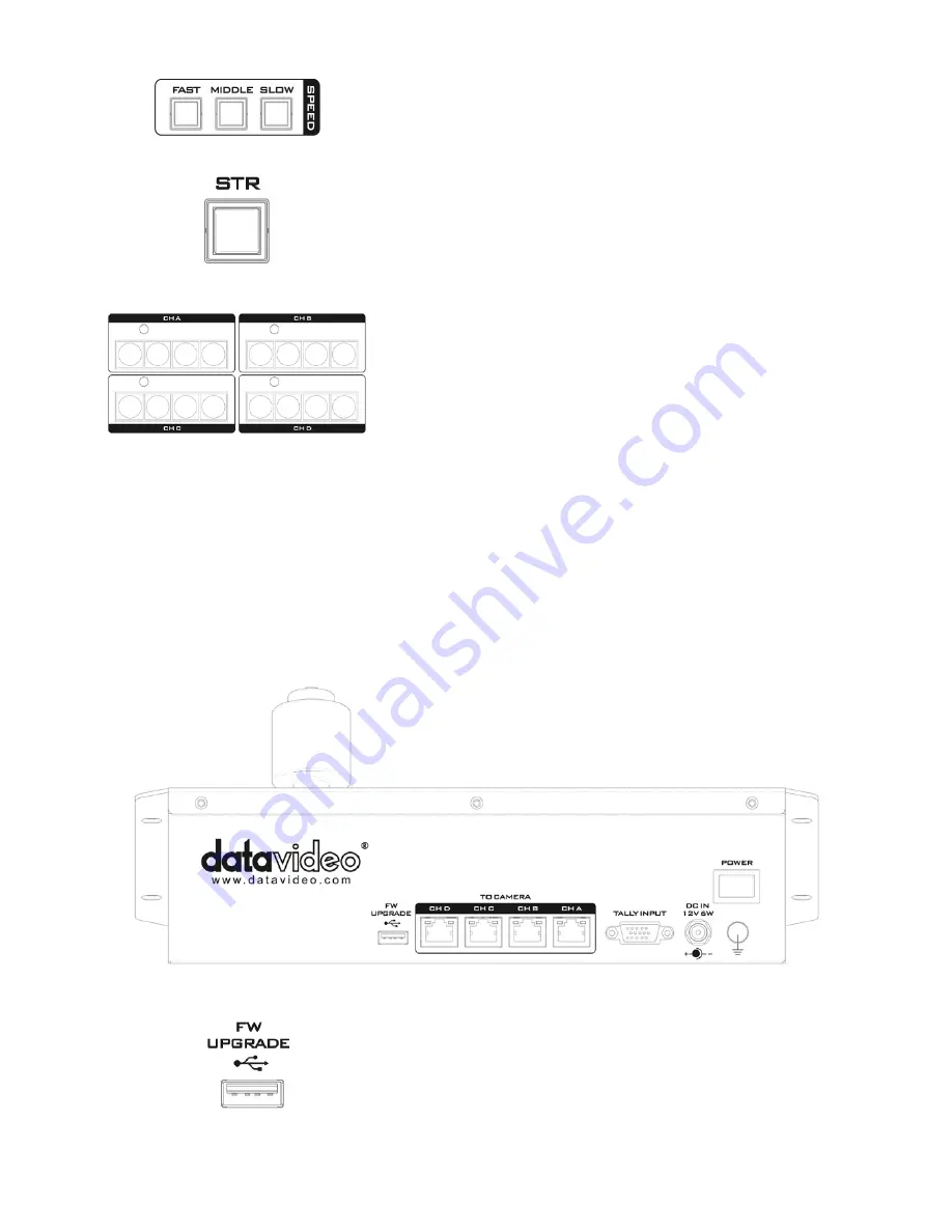
Speed
The speed at which the selected camera moves can be chosen by
pressing one of the three speed buttons.
STR
Pressing this button enters the RMC-180 into STORE MODE.
When activated, this allows the current camera position to be
stored in a chosen Channel Memory Button. Press again to exit
STORE MODE.
Channel Memory Buttons
These buttons may be used to store up to four camera positions
for each camera. Each button corresponds to one stored camera
position. The activated button LED will be turned ON.
Tally Indicator LEDs
Each set of the four memory buttons is assigned a Tally Indicator
LED. This LED feature becomes active when the RMC-180 is
connected to the tally output of a compatible Datavideo
Switcher such as the HS-2000 or HS-2200.
When the HS-2000 or HS-2200 Switcher is sending camera A’s
video to the program output, the RMC-180 CH A’s tally LED will
be turned ON. Additional equipment and cabling are required.
2.2 Rear Panel – Connections
Firmware Upgrade
USB type A port for connection to a computer during the
firmware upgrade process.


