


9
3.
Functions
In this section, the user will be introduced the individual functions of the PTZ
camera and the receiver box that comes with the product package.
3.1
PTZ Camera
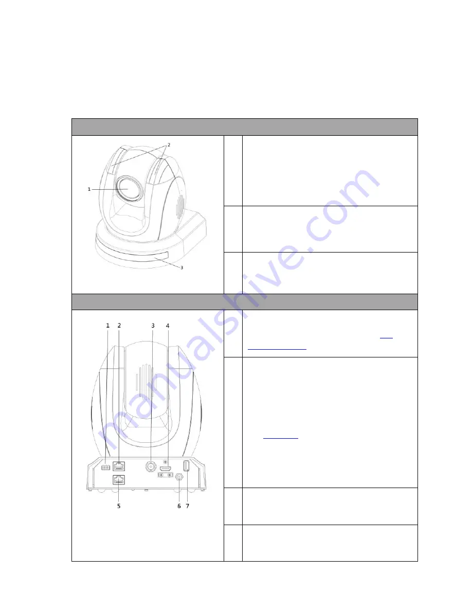
Front of Camera
1
Lens
Built-in 1/2.3
”
8.93M Pixel CMOS HD color
camera with white balance control,
backlight compensation settings, automatic
gain settings and etc.
2
Tally LED
Tally lamp lights up when tally signal has
been received.
3
Sensor for Remote Control
Remote controller receiver
Rear of Camera
1
DIP Switch SW2
DIP switch for IRID setting.
See the
DIP
Switch Settings
section for details.
2
RS422 Communication Port
Connection to the RMC-180 PTZ Camera
Control Unit for remote control of the
camera via any RJ-45 cable.
See
Section 8
for physical connection to
the RMC-180. For details on how to use
the RMC-180, please read the RMC-180
instruction manual.
3
3G-SDI OUT
Video signal output
4
HDMI OUT
Video signal output


