background image

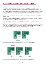
Connecting a VSN900X-Optical Expansion Chassis

The Optical Solution

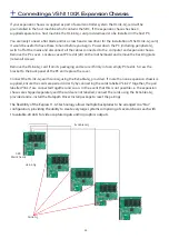
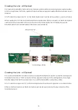
The Datapath optical solution allows expansion chassis to be located up to 100m away from the main  
controller.  The Optical solution can support up to PCIe Gen 3 x8  bandwidths between an HLink-Optical,  
located in the host machine and an SLink-Optical, located in the expansion chassis  Full bandwidth is 
achieved by using two ExCable-Optical cables between each HLink and SLink-Optical card .  

Alternatively, PCIe Gen3 x4 bandwidth can be achieved using only one ExCable-Optical between each 
HLink-Optical and SLink-Optical.  This will reduce the total amount of video signal that can be transferred 
between the chassis.  If x4 bandwidth is acceptable, one HLink-Optical can be connected to two  
SLink-Optical cards, providing that the HLink-Optical is located in a x8 slot.  

See 

Creating the link x4 and x8

 on page 15.

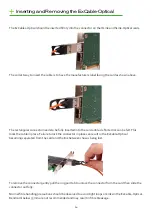
If your optical expansion chassis is supplied as part of a complete wall controller system the HLink-Optical 
card will be pre-installed in the host machine which contains the SBC. If the expansion chassis has been 
supplied separate to a host machine the HLink-Optical card provided needs to be installed in the host PC.

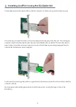
You are likely to need a flat blade and/or a cross head screwdriver for the installation of the HLink-Optical 

card; it would be useful to have these to hand before you begin. Power down the PC (including  

peripherals), switch off at the mains and disconnect all the cables connected to the computer and 


expansion chassis. Remove the PC cover. Locate a vacant PCIe slot (x8 on the motherboard and remove 
the backing plate (retain all screws) .

Remove the HLink-Optical card from its packaging and secure it firmly into the empty PCIe slot. Screw the 

bracket to the back panel of the PC and replace the cover.

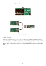
Connect the HLink-Optical and SLink-Optical using the ExCable-Optical provided. If more than one  
expansion chassis is supplied, ensure the cards are paired correctly by connecting the cards labelled 
“Link1” together, the pair labelled “link2” are connected together and so on. In the event that this is not 
possible i.e. the expansion chassis are shipped separately and the cards are not labelled, connect the cards 
using the ExCables-Optical provided and re-install the Datapath Driver Install package to reset the  
pairings.

PCI Express Gen.3 technology supports one directional data transfer speeds of up to 8GB/s of raw data 

(6.4GB/s effective data rate) ensuring smooth, full frame rate video distribution over great distances. 

Connecting to a VSN970/VSN990 Wall Controller

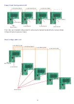
If the VSN900X-Optical is being connected to a VSN970 or VSN990 and the full bandwidth (x8) is required 

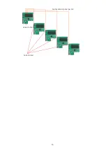
then dual optical cables should be used and the “Daisy Chain” configuration adopted.  This is achieved by 
installing the HLink-Optical card on the first slot of the VSN970/VSN990 and the first slot of each 


subsequent VSN900X expansion chassis.  Only the first slot of the Express9-G3 backplane is able to 


support the full x8 Gen.3 connection.  Using other slots on the backplane or adopting a “Star”  

configuration i.e. a single HLink-Optical in a host system connected to 2 x SLink-Optical in separate 


expansion chassis will still work but at a  reduced bandwidth (x4).  

9

Summary of Contents for VSN900X

Page 1: ...VSN900X VSN1100X Version 1 1 User Manual Expansion Chassis...

Page 2: ...onnecting aVSN900X Expansion Chassis 8 Connecting aVSN900X Optical Expansion Chassis 9 Connecting aVSN1100X Expansion Chassis 11 Connecting aVSN1100X Optical ExpansionChassis 12 Inserting and Removing...

Page 3: ...h Produkt undVerletzungen der Nutzer Bitte lesen Sie sie sorgf ltig durch bevor Sie Ihr Produkt in Betrieb nehmen Diese Anweisungen sollten allen Personen zug nglich gemacht werden die mit der Nutzung...

Page 4: ...G3 SLink G3 installed 9 VSN1100X Express11 G3 SLink G3 installed 11 VSN900X Optical Express9 G3 SLink Optical installed 9 VSN1100X Optical Express11 G3 SLink Optical installed 11 Connecting multiple...

Page 5: ...Gen3 VSN900X Optical 9 slot expansion system providing 8 PCIe gen3 x4 slots 1 PCIe gen2 x8 slot 1 x8 PCIe Gen3 VSN1100X 11 slot expansion system providing 11 PCIe Gen3 x8 slots VSN1100X Optical 11 slo...

Page 6: ...6 Components HLink G3 SLink G3 ExCable G3 HLink Optical SLink Optical ExCable Optical...

Page 7: ...nector Top Connector Bottom Connector 1 x x x x x x 1 1 x x x x 2 2 N A x x x x 3 N A x x x x 4 N A x x x x 5 N A x x x x 6 N A x x x x 7 N A x x x x 8 N A x x x x 9 N A x x x x 1 SLink Optical card i...

Page 8: ...ll screws Remove the HLink G3 card from its packaging and secure it firmly into the empty PCIe slot Screw the bracket to the back panel of the PC and replace the cover Connect the HLink G3 and SLink G...

Page 9: ...sis Remove the PC cover Locate a vacant PCIe slot x8 on the motherboard and remove the backing plate retain all screws Remove the HLink Optical card from its packaging and secure it firmly into the em...

Page 10: ...al 2 x ExCable Optical 2 x ExCable Optical 2 x ExCable Optical 10 This is the recommended configuration for achieving the highest bandwidth when using multiple VSN900X Optical expansion chassis Star C...

Page 11: ...HLink G3 card from its packaging and secure it firmly into an empty PCIe slot Screw the bracket to the back panel of the PC and replace the cover Connect the HLink G3 and SLink G3 using the ExCable G...

Page 12: ...nnect all the cables connected to the computer and expansion chassis Remove the PC cover Locate a vacant PCIe slot x8 on the motherboard and remove the backing plate retain all screws Remove the HLink...

Page 13: ...13 HLink Optical SLink Optical Dual ExCable Optical per link...

Page 14: ...ks the cable in place Failure to lock the connector in place can result in the ExCable Optical becoming separated from the card and the link between chassis being lost Inserting and Removing the ExCab...

Page 15: ...ctor on the SLink Optical card Similarly the second ExCable Optical must connect between the lower card connectors Jumper Link J7 Connecting a x8 link Creating the Link x4 Optical For a reduced bandwi...

Page 16: ...ame locking It is assumed that displays controlled from the expansion chassis would be sufficiently far away from the host machine that this will not be a problem It should be noted that all displays...

Page 17: ...ully inserted into the card until a definite click can be felt This locks the cable in place Failure to lock the connector in place can result in the ExCable G3 becoming separated from the card and th...

Page 18: ...DegF StorageTemperature 20 to 70 DegC 4 158 DegF Relative Humidity 5 to 90 non condensing Noise 48 6dB A upto 67 9dB A Dependent on system configuration ambient temperature DIMENSIONS Length 500mm inc...

Page 19: ...ath Web Site usually with a response within 24 hours excluding weekends Via Email Send an email to support datapath co uk with as much information about your system as possible To enable a swift respo...

Page 20: ...xpress11 G3 11 F Features 4 Frame locking 16 H HLink G3 6 HLink Optical 6 Host PC 8 I Inserting the cable 17 20 Index Installing the HLink G3 card 11 Installing the HLink Optical 12 J Jumper Link J7 1...

Reviews: