


TC1100
12
2
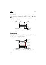
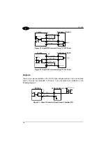
RS232 Interface
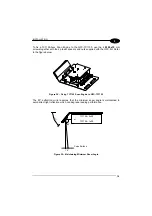
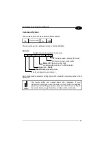
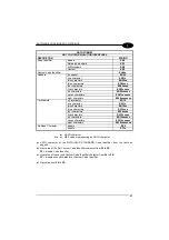
The TC1100 Scan Engine can communicate with the Host using the RS232 signals
provided on the J1 connector. The pins are indicated in Table 1 and in the following
diagram:
It is always advisable to use shielded cables. The overall maximum cable length
must be less than 15 m (49.2 ft).
TC1100
1
7
5
6
SGND
RTS
CTS
RX
TX
8
Host
SGND
DCD
DTR
TXD
RXD
Earth
Ground
J1
Figure 14 - RS232 Interface Connection to Host
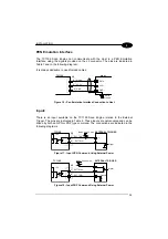
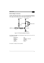
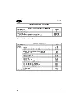
WEDGE Interface
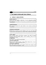
The TC1100 Scan Engine can communicate with the Host in a WEDGE Interface
(Keyboard Emulation) using the signals provided on the J2 connector. The pins are
indicated in Table 1 and in the following diagram:
TC1100
5
DATAIN
3
CLKOUT
4
DATAOUT
2
GND
VCC+
1
J2
6
CLKIN
Host
GND
VCC+
CLK
DATA
Keyboard
DATA
CLK
GND
VCC+
Figure 15 - Wedge Interface Connection to Host (PC AT) and Keyboard
Summary of Contents for TC1100
Page 1: ...TC1100 Installation Manual ...
Page 2: ...TC1100 Reference Manual ...
Page 3: ...TC1100 REFERENCE MANUAL ...
Page 128: ...TC1100 120 A ...


