Installation Manual
Rhino™ 10
1. Press Power to suspend the Rhino™ 10.
2. Disconnect the power cable.
3. If you have an external antenna, remove the right antenna.
4. Unscrew the four hex head screws from the right top cover and gently remove the cover. If you have an
external antenna, do NOT remove the antenna cable; simply let it hang on the unit. Make sure you
keep all of the screws.
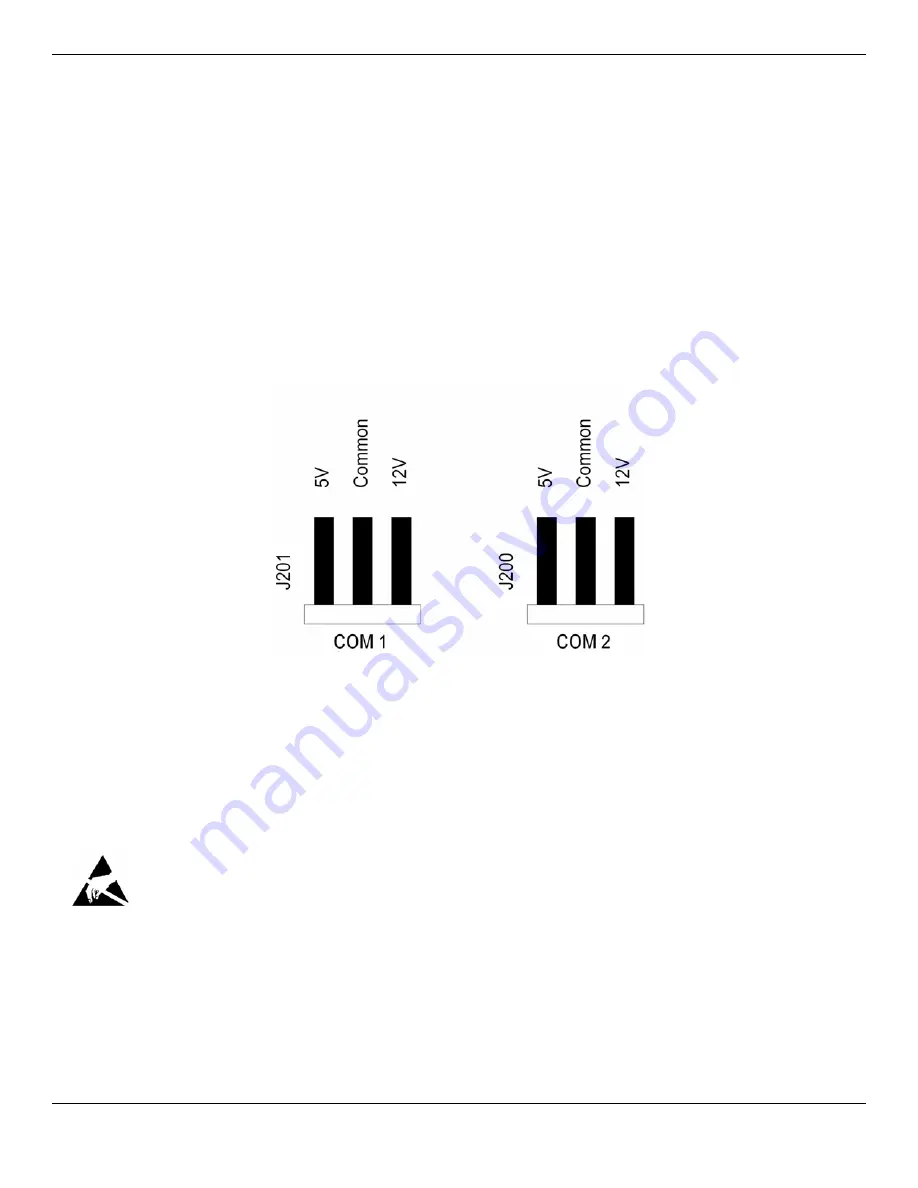
5. Select the voltage required for each serial port by moving the jumper between common and 5 volt or 12
volt pin. If no voltage is required, either remove the jumper, or connect it in a vertical orientation to the
center pin only. Factory default is 5V on both COM 1 and COM 2.
6. Replace the top cover, and attach it with the four screws you removed in Step 2. Lightly tighten with
even torque on all four screws.
Figure 14 – Serial Port Voltage Jumpers
Increasing Memory Storage
You can use an SD or SDHC card to increase file storage and install software. The Rhino™ 10 currently supports
SDHC cards that hold up to 32 GB of information. The SD card slot is located on the top of the Rhino™ 10 under the
left top cover. You must remove the top cover using a 1/16” Allen driver to access the SD card slot.
This operation requires an ESD protected workstation!
Failure to prevent ESD damage may void the warranty. If in doubt, have an authorized Datalogic Partner
perform this installation for you.
Inserting an SD card
1. Press Power to suspend the Rhino™ 10.
2. Disconnect the power cable.
3. If you have an external antenna, remove the left antenna.
4. Unscrew the four hex head screws from the left top cover and gently remove the cover. If you have an external
antenna, do NOT remove the antenna cable. Simply let it hang on the unit. Make sure you keep all of the
screws.
14


