background image

MAINTENANCE AND DIAGNOSTICS

_____________________________________

A

Ed.: 01/99

37

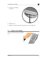
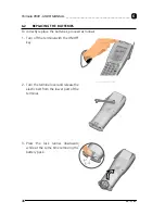
4 - Insert the new battery pack,

keeping the lock runner
pressed down. 
Once the battery pack is cor-
rectly inserted, release the lock
runner.

CAUTION

Dispose of the batteries as
required by the relevant laws
in force.

6.3

CLEANING THE TERMINAL

Periodically clean the terminal with a slightly dampened cloth. 
Do not use alcohol, corrosive products or solvents.

Summary of Contents for Formula 8500

Page 1: ...Formula 8500 USER MANUAL 200175985020 ENGLISH ...

Page 2: ...s mentioned herein are for identificationpurposes only and may be trademarks and or registred trademarks of their respective companies 1997 1998 Datalogic S p A Datalogic S p A Via Guglielmo Marconi 161 31021 Mogliano Veneto TV Italy Tel int 041 598 6511 Fax int 041 598 6550 C Formula 8500 USER MANUAL Ed 01 99 Code 200175985020 ...

Page 3: ...RAL SAFETY RULES 8 3 2 MAINTENANCE SAFETY 9 3 3 DANGER SIGNALS 9 3 4 U S FEDERAL COMMUNICATIONS COMMISSION RADIO FREQUENCY INTERFERENCE STATEMENT INFORMATION TO THE USER 10 4 CONNECTIONS 11 4 1 TERMINAL CONNECTION TO THE HOST COMPUTER 11 4 1 1 RS 232 Connection 11 4 1 2 Other types of connection 13 4 2 CRADLE F985 16 4 2 1 F985 cradle 18 4 2 2 F985 vehicle cradle 19 3 1 CONNECTION CABLES 20 5 USE ...

Page 4: ...___________________ 5 3 BAR CODE SCANNING 26 5 4 DESCRIPTION OF THE KEYS 27 6 MAINTENANCE AND DIAGNOSTICS 35 6 1 CHARGING THE BATTERIES 35 6 2 REPLACING THE BATTERIES 36 6 3 CLEANING THE TERMINAL 37 A PRODUCTS AND ACCESSORIES OF THE FORMULA 8500 LINE 38 ...

Page 5: ...s of use these chapters are for whomever uses the terminal in their day to day work activity Chapters 4 5 6 which define the connections methods for the terminal These chapters are aimed at the person responsible for managing the terminals generally the person who installs the network and the application program Constant attention to the indications contained in the manual will guarantee the user ...

Page 6: ...essories necessary for the terminal connec tion to the host computer and to the network the cradle power supply and one or more connection cables Remove all the components from their packaging check their integrity and congru ity with the packing documents Keep the original packaging for use when sending products to the technical assis tance centre Damage caused by improper packaging are not cover...

Page 7: ...N ______________________________________________ 1 Ed 01 99 3 1 4 TERMINAL MANUFACTURER AND MODEL IDENTIFICATION Serial Number 2007900111 F8500 140734500 Volt Code Model identification and serial number Model description ...

Page 8: ...tion of modems Ethernet and Token Ring adapters and solid state disk using the standard PC Card technology The Formula 8500 is equipped with an IrDA port for short range wireless infrared communication with portable printers and other devices that support this kind of interface The Formula 8500 is equipped whit a back light LCD graphic display with 160 by 240 pixels reso lution and an ergonomic al...

Page 9: ... the code 30 800 mm Light source laser scanner VLD source 670 nm Scan rate 570 20 scan sec Frame rate 25 frames sec Minimum resolution 0 15 mm Skew or yaw angle 15 Pitch or Roll angle 30 Depth of field depends on the type and density of the code 75 300 mm 2D codes 120 700 mm 1D codes Micro controller 32 bit AMD 486 Memory BIOS DOS 512KB Flash memory Disk memory 2 4 8 MB RAM 2 4 MB DRAM EEPROM 256 ...

Page 10: ...Keyboard 41 keys in silicone covered rubber reset key Temperature working temperature 0 up to 45 C storage 20 up to 60 C 20 35 Cforlongtermbatterystorage Relative Humidity 95 without condensation Degree of protection EN 60529 IP 51 Electrostatic discharge IEC 1000 4 2 up to 15KV on air Resistance to falls IEC 68 2 32 up to 1 2 m on concrete Safety standards IEC 825 class 2 laser product Operating ...

Page 11: ... on 5 UPC A add on 2 add on 5 UPC E add on 2 add on 5 UCC EAN 128 Interleaved 2 of 5 ITF Codabar Monarch NW7 2 of 7 Code 39 Code 39 full ASCII Code 93 Code 128 MSI PDF 417 Optical Interface IrDA 1 0 F985 Interface cradle terminal interface via IrDA Cradle Host Interface RS 232 RS 485 Eavesdrop Maximum speed of transmission 115 Kbit sec max Frequency 2 4 GHz Power output 100 mW Max In compliance wi...

Page 12: ... used on this terminal can be dangerous for one s eyesight if looked at directly or for long periods of time For this reason avoid directing the laser beam towards your eyes or those of other people or animals Use only the components supplied by the manufacturer for the specific terminal being used The use of cradles other than those supplied with the terminal or in dicated in the list in the appe...

Page 13: ...y the user Any tampering will invalidate the guarantee When replacing the batteries or at the end of the operative life of the terminal disposal must be performed in compliance with the law in force Do not submerge the terminal in liquid products 3 3 DANGER SIGNALS CAUTION Be sure the danger labels applied on the terminal are readable at all times If necessary replace them with new ones ...

Page 14: ...r ference to radio communications However there is no guarantee that interference will not occur in a particular in stallation If this equipment does cause harmful interference to radio or television reception which can be determinated by turning the equipment off and on the user is en couraged to try to correct the interface by one or more of the following measures Re orient the receiving antenna...

Page 15: ...rry out the nec essary physical connections as indicated below 1 take out the cable contained in the cradle package and connect it to the COM1 serial port or another available serial port using connector DB9 2 connect the other end of the same cable to the RS 232 port of the cradle with the RJ connector 3 insert the power supply plug into the outlet on the base of the cradle 4 attach the power sup...

Page 16: ...00 USER MANUAL __________________________________________ 4 Ed 01 99 12 5 put the terminal into its cradle and if necessary recharge the battery Key A Host computer B Cradle F985 C Cradle power supply FPS14 A B C ...

Page 17: ...nables the terminal to be connected on an existing asynchronous RS 232 line for example between the host computer and a video terminal Key A Video terminal B Host Computer C Cradle F985 D Cradle power supply RS 485 Connection Allows for the connection of more terminals on a single RS 232 line through the installation of a Sysnet network If the Sysnet network is made using the Formula 902 T Box up ...

Page 18: ...___________________________ 4 Ed 01 99 14 Key A Host computer B Formula 902 T box C Cradle F985 D Cradle power supply E Formula 904 N Interconverter F P S 1 4 Formula 904 N Formula 902 Formula 902 F P S 1 4 Formula 902 Power Supply A B C D E ...

Page 19: ...s the terminal to be connected to the host computer via radio frequency using the RF PCMCIA module that is with the F8500 only for RF version and an Access Point connected to the host computer Key A F8500 B Access Point APPLICATION SERVER ETHERNET TOKEN RING ACCESS POINTS ACCESS POINTS SEAMLESS ROAMING A B ...

Page 20: ... cradle can be used with the Formula 8500 terminal Key F985 standard A IrDA window B Two color LED spare battery slot C Terminal recharge contacts D Two color LED terminal battery E Contacts for recharging the spare battery F Connectors for connecting to the host computer G Power supply connector A B C D E F G F ...

Page 21: ...CONNECTIONS________________________________________________________ 4 Ed 01 99 17 Key F985 vehicle cradle A Cradle F985 B Clip in craddle C Metal bracket B A C ...

Page 22: ...ed The LED D indicates the status of the batter ies in the terminal The spare batteries can also be charged by in serting them into the back part of the cradle making sure the contacts E are correctly po sitioned The LED B indicates the status of the batter ies in the terminal COLOR DESCRIPTION Constant red Battery charging Flashing red green Battery charged terminal on Constant green Battery char...

Page 23: ... have a stabilised power supply connected to the vehicle s battery The power supply must have the following output characteristics ATTENTION Do not connect the cradle directly to the vehicle s battery Possible voltage surges can damage the cradle or cause it to malfunction 3 Insert the F8500 terminal only after mounting the cradle in the vehicle ATTENTION We recommend that you detach any connectio...

Page 24: ...cables are listed with their number code C and production batch number RS 232 connection with PC AT or compatible cable C407900330 404682100 RS 232 connection with PC XT or compatible cable C407900310 404682200 RS 485 connection cable C407900300 303350260 RJ DB 9M SIGNAL 1 2 TX 2 8 RTS 3 5 GND 4 7 CTS 5 3 RX 4 1 RJ DB 25M SIGNAL 1 3 TX 2 5 RTS 3 7 GND 4 4 CTS 5 2 RX 8 20 RJ SIGNAL 3 GND 6 RX TX 7 ...

Page 25: ... 21 Modem or Eavesdrop connection with host computer cable C407900020 404613020 Eavesdrop connection with terminal cable C407900030 404613030 RJ DB 25M SIGNAL SIGNAL 1 2 TX 2 4 RTS 3 7 GND 4 5 13 CTS RX 5 3 12 RX RX 6 15 TX 7 14 TX RJ DB 25M SIGNAL 1 3 TX 2 2 RX 3 7 GND 4 5 8 20 ...

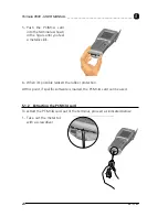
Page 26: ...ith the required function For example peripherals can be connected to the terminal including a network card an RF communication card a modem fax or a flash disk capable of storing tens of Megabytes 5 1 1 Inserting the PCMCIA card To insert the PCMCIA card into the terminal proceed as indicated below 1 Remove the rubber protection ...

Page 27: ...___________________________________________ 5 Ed 01 99 23 2 Use a screwdriver to lever out the metal tab shown in the figure 3 Pull the tab outwards until you feel its end stop 4 Insert the card with the main side facing down ...

Page 28: ...shown in the figure until you feel a metallic click 6 When it s possible reinsert the rubber protection At this point if specific software is loaded the PCMCIA card can be used 5 1 2 Extracting the PCMCIA card To extract the PCMCIA card out of the terminal proceed as indicated below 1 Take out the metal tab with a screwdriver ...

Page 29: ...________________________ 5 Ed 01 99 25 2 Pull the tab outwards to its end stop 3 Extract the card 4 Reinsert the metal tab into the terminal until you feel a metallic click 5 2 TURNING ON THE TERMINAL To turn on the terminal press the ON OFF key ...

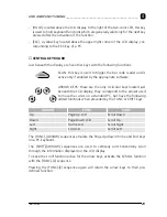
Page 30: ...while pressing the SCAN key The lighted band emitted by the laser must completely intercept the bar code the LED and the emission of an acoustic signal if enabled will indicate that the scan has taken place correctly INFORMATION The heat that can be felt in the area of the battery pack is not a symptom of a malfunction rather it is a normal state due to the terminal being in use NO NO OK OK ...

Page 31: ...______________________________ 5 Ed 01 99 27 5 4 DESCRIPTION OF THE KEYS Key A Laser beam outlet window B Programmable two color LEDs C Keyboard D Protected reset button E F985 cradle communication window F Antenna G Pen hole A B E D F C G ...

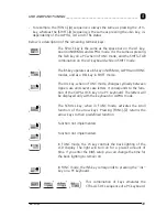
Page 32: ...ve the upper left corner of the LCD display this button turns the terminal on and off CONTRAST located just to the right of the ON OFF key and identifiable by a half black and half white circle this button is used to adjust the display contrast by pressing the button repeatedly and releasing it between one press and the next for less than a second you will alter the contrast always in the same dir...

Page 33: ...opriate software ARROW KEYS these are the only 4 circular keys located just beneath the LCD display they correspond to the arrows used to move the cursor on a standard PC but have the following added functions when preceded by the FUNC or SHIFT keys The FUNC ARROW sequences emulate the Page Up Down Home and End keys on a PC keyboard The SHIFT ARROW sequences are used to vertically and horizontally...

Page 34: ...eys and located at the centre of the right hand column 28 general keys marked with 2 3 or 4 symbols Three special keys ALPHA FUNC SHIFT to change the keyboard mode ENTER corresponds to the ENTER key on a PC GENERAL KEYS the 28 keys that carry extra symbols their function changes according to the various key board functions To explain their function the key is logically divided into 4 sections acco...

Page 35: ... symbol NORMAL mode The keyboard remains in this mode till the ALPHA key is pressed again FUNC MODE Switches keyboard to the function FUNC mode from the ALPHA or NORMAL mode The keyboard remains in this mode only when the next general key is pressed then it returns to the previous mode For example to press the F1 key press the FUNC A in sequence SHIFT MODE On the F8500 the SHIFT key is not pressed...

Page 36: ... A key from the ALPHA mode press the SHIFT ALPHA A keys in sequence For example to press the ALT F1 key press the SHIFT AL PHA FUNC A keys in sequence If the HOLD key is pressed immediately after the ALT or CTRL modes have been activated the keyboard will remain in the ALT or CTRL mode for the entire key se quence of keys till the next SHIFT ALPHA sequence in ALT mode or SHIFT FUNC in CTRL mode To...

Page 37: ...a DEL key in SHIFT mode The U L key when in FUNC mode changes cyclically between Upper case and Lower case letters It corresponds to the func tion of the CAPS LOCK key on a PC keyboard The letters will be displayed only with the keyboard in ALPHA mode The SCROLL key when in FUNC mode activates the scroll function of the arrow keys Pressing FUNC Z returns the arrow keys to their predefined function...

Page 38: ..._____________________ 5 Ed 01 99 34 This combination of keys emulates the CTRL BREAK sequence of a PC keyboard PROTECTED RESET BUTTON to activate the reset button insert a blunt ended object into the hole The reset function will delete all RAM data ...

Page 39: ... recharged for a long time you will have to perform two or three charge and discharge cycles complete use before they are capable of reaching their greatest charge capacity CAUTION If the terminal will not be used for a few days we recommend that the battery pack be removed from the terminal to prevent the battery from being damaged from over discharging CAUTION The time required to recharge a com...

Page 40: ...LACING THE BATTERIES To correctly replace the batteries proceed as follows 1 Turn off the terminal with the ON OFF key 2 Turn the terminal over and release the elastic belt from the lower part of the terminal 3 Press the lock runner downward while at the same time removing the battery pack ...

Page 41: ...ing the lock runner pressed down Once the battery pack is cor rectly inserted release the lock runner CAUTION Dispose of the batteries as required by the relevant laws in force 6 3 CLEANING THE TERMINAL Periodically clean the terminal with a slightly dampened cloth Do not use alcohol corrosive products or solvents ...

Page 42: ...5 Transceiver charger Battery charger and optical transceiver for connections between terminal and host computer in RS 232 and RS 485 Formula F985 Vehicle Transceiver charger Battery charger and optical transceiver for connections between terminal and host computer in RS 232 and RS 485 It s possible to install it inside a vehicle driving compartment Batteries NiMH Battery Pack Radio Frequency Form...

Page 43: ...tiven des Europäischen Rats cumple con los requisitos de las Directivas del Consejo Europeo según la lista siguiente Basate sulle legislazioni degli Stati membri in relazione alla compatibilità elettromagnetica ed alla sicurezza dei prodotti On the approximation of the laws of Member States relating to electromagnetic compatibility and product safety Basée sur la législation des Etats membres rela...

Page 44: ......

Reviews: