background image


DS6500 DEVICENET MODEL


The details of the connector pins are indicated in the following table: 


26-pin D-Sub Connector Pinout 

Pin Name 

Function 

Chassis - internally connected to GND 

1 CHASSIS 

Cable shield connected to chassis 

20 

RXAUX 

Receive data of auxiliary RS232 (referred to GND) 

21 

TXAUX 

Transmit data of auxiliary RS232 (referred to GND) 

OUT 1+ 

Configurable digital output 1 – positive pin 

22 OUT 

1- 

Configurable 

digital output 1 – negative pin 

11 OUT 

2+ 

Configurable 

digital output 2 – positive pin 

12 OUT 

2- 

Configurable 

digital output 2 – negative pin 

16 OUT 

3A 

Configurable 

digital 

output 3 – polarity insensitive 

17 OUT 

3B 

Configurable 

digital 

output 3 – polarity insensitive 

18 EXT_TRIG/PS 

External 

trigger 

(polarity insensitive) for PS 

19 EXT_TRIG/PS 

External 

trigger 

(polarity insensitive) for PS 

IN2/ENC A 

Input signal 2 (polarity insensitive) for Encoder 

10 

IN2/ENC B 

Input signal 2 (polarity insensitive) for Encoder 

14 

IN3A 

Input signal 3 (polarity insensitive) 

15 

IN4A 

Input signal 4 (polarity insensitive) 

24 

IN_REF 

Common reference of IN3 and IN4 (polarity insensitive) 

9, 13 

VS 

Supply voltage – positive pin 

23, 25, 26  GND 

Supply voltage – negative pin 


10

19

18

9

26

26-pin male D-sub Connector

Pin 

RS232 

RS485 Full-Duplex 

RS485 Half-Duplex


20 mA C.L 

(INT-30 with C-BOX 100 only)

2 TX 

TX485+  


3 RX 

RX485+ 


RTS 

TX485- 

RTX485- 

see INT-30 instructions 

5 CTS 

RX485- 


7 GND_ISO  GND_ISO  GND_ISO 


For 20 mA C.L. connections, GND is the same of the scanner power supply. 


9-pin Lonworks Connector Pinout 

Pin Name 

Function 

Cable shield internally connected 

1 CHASSIS 

by capacitor to chassis 

VS 

Supply voltage – positive pin 

GND 

Supply voltage – negative pin 

VS_I/O 

Supply voltage of I/O circuit 

3 Ref_I/O 

Reference voltage of I/O circuit 

4 SYS_ENC_I/O 

System 

signal 

5 SYS_I/O 

System 

signal 

LON A 

Lonworks line (polarity insensitive) 

LON B 

Lonworks line (polarity insensitive) 


5


1


9


6


9-pin female Local Lonworks Connector 


5-pin DeviceNet Connector Pinout 

Pin Name 

Function 

V+ 

Supply voltage – positive pin 

CAN_L 

CAN bus data line – L 

1 SHIELD 

Shield 

CAN_H 

CAN bus data line – H 

V- 

Supply voltage – negative pin 


1

4

5


5-pin male DeviceNet Connector 


NOTE 

The power supplied on pin V+ and V- is used only to propagate power to the section of the 
DeviceNet board directly connected to the Bus. It is completely isolated from the DS6500 power 
which must be supplied on pin 9, 13 and pin 23, 25 of the 26-pin Main/Aux connector. 

20  


Summary of Contents for DS6500 Series

Page 1: ...DS6500 INSTALLATION QUICK REFERENCE...

Page 2: ...DS6500 100 012 ETHERNET MODEL 13 DS6500 100 015 DEVICENET MODEL 18 DS6500 105 0XX OSCILLATING MIRROR MODEL 23 COMMON FEATURES 25 NOTE For further details on product installation see the complete Refer...

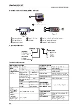
Page 3: ...che photodiode Wavelength 630 to 680 nm Power Consumption 15 W typical 20 W Max including startup current Main isolated Baud Rate Safety Class Class 2 EN 60825 1 Class II CDRH RS232 RS485 full duplex...

Page 4: ...to C BOX100 10 m 93A051271 CAB 6101 Cable master slave 1 m 93A051220 CAB 6102 Cable master slave 2 m 93A051230 CAB 6105 Cable master slave 5 m 93A051240 CAB 6112 Cable master slave no power 2 m 93A05...

Page 5: ...IN_REF Common reference of IN3 and IN4 polarity insensitive 9 13 VS Supply voltage positive pin 23 25 GND Supply voltage negative pin 14 1 25 13 25 pin male D sub Connector Pin RS232 RS485 Full Duplex...

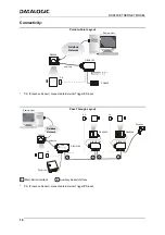
Page 6: ...ence Sensor connected to External Trigger PS input Pass Through Layout E N T E N T P S P S Gryphon DS4600A DS4600A DS6500 CAB 600X C BOX 100 C BOX 100 C BOX 100 AUX MAIN P S 2 2 1 1 Local Host 1 PWR 1...

Page 7: ...ost 1 RS485 HD Main Interface P S Presence Sensor connected to External Trigger PS input RS232 Master Slave Layout E N T E N T DS6500 Master CAB 600X C BOX 100 DS4600A Slave 1 1 2 P S Local Host 1 C B...

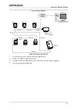
Page 8: ...d to accept scanner power Encoder connected to IN2 ENC input Local Lonworks Network Slave 2 Slave 1 Master C BOX 100 BTK 6000 CAB 610X CAB 610X CAB 600X P S CAB 610X Encoder Host CAB 610X CAB 610X CAB...

Page 9: ...00 MASTER SLAVE MODEL Large Synchronized Network P S Presence Sensor connected to External Trigger PS input Encoder connected to IN2 ENC input Large Synchronized Network with DX6X00 and DS6XXX Scanner...

Page 10: ...diode Wavelength 630 to 680 nm Power Consumption 15 W typical 20 W Max including startup current Main isolated Baud Rate Safety Class Class 2 EN 60825 1 Class II CDRH RS232 Laser Control Security syst...

Page 11: ...to C BOX100 1 m 93A051221 CAB 6012 Cable to C BOX100 2 m 93A051222 CAB 6015 Cable to C BOX100 5 m 93A051223 C BOX 100 Passive connection box 93ACC1510 INT 30 20 mA C L interface board for C BOX 100 9...

Page 12: ...ly voltage positive pin 23 25 26 GND Supply voltage negative pin 10 19 1 18 9 26 26 pin male D sub Connector Pin RS232 RS485 Full Duplex RS485 Half Duplex 20 mA C L INT 30 with C BOX 100 only 2 TX TX4...

Page 13: ...sence Sensor connected to External Trigger PS input Pass Through Layout Remote Host E N T E N T P S P S Gryphon Fieldbus Network DS4600A DS4600A DS6500 CAB 601X C BOX 100 C BOX 100 AUX C BOX 100 P S 2...

Page 14: ...Encoder CAB 610X CAB 610X CAB 63XX BTK 6000 Slave 3 Slave 5 Slave 4 PWR 240 CAB 63XX Fieldbus Small Synchronized Network P S Presence Sensor connected to External Trigger PS input C BOX 100 modified...

Page 15: ...diode Wavelength 630 to 680 nm Power Consumption 15 W typical 20 W Max including startup current Main isolated Baud Rate Safety Class Class 2 EN 60825 1 Class II CDRH RS232 Laser Control Security syst...

Page 16: ...to C BOX100 1 m 93A051221 CAB 6012 Cable to C BOX100 2 m 93A051222 CAB 6015 Cable to C BOX100 5 m 93A051223 C BOX 100 Passive connection box 93ACC1510 INT 30 20 mA C L interface board for C BOX 100 93...

Page 17: ...N4A Input signal 4 polarity insensitive 24 IN_REF Common reference of IN3 and IN4 polarity insensitive 9 13 VS Supply voltage positive pin 23 25 26 GND Supply voltage negative pin 10 19 1 18 9 26 26 p...

Page 18: ...sence Sensor connected to External Trigger PS input Pass Through Layout Remote Host E N T E N T P S P S Gryphon Fieldbus Network DS4600A DS4600A DS6500 CAB 601X C BOX 100 C BOX 100 AUX C BOX 100 P S 1...

Page 19: ...Encoder CAB 610X CAB 610X CAB 63XX BTK 6000 Slave 3 Slave 5 Slave 4 PWR 240 CAB 63XX Fieldbus Small Synchronized Network P S Presence Sensor connected to External Trigger PS input C BOX 100 modified...

Page 20: ...Wavelength 630 to 680 nm Power Consumption 15 W typical 20 W Max including startup current Main isolated Baud Rate Safety Class Class 2 EN 60825 1 Class II CDRH RS232 Laser Control Security system to...

Page 21: ...able to C BOX100 1 m 93A051221 CAB 6012 Cable to C BOX100 2 m 93A051222 CAB 6015 Cable to C BOX100 5 m 93A051223 C BOX 100 Passive connection box 93ACC1510 INT 30 20 mA C L interface board for C BOX 1...

Page 22: ...23 25 26 GND Supply voltage negative pin 10 19 1 18 9 26 26 pin male D sub Connector Pin RS232 RS485 Full Duplex RS485 Half Duplex 20 mA C L INT 30 with C BOX 100 only 2 TX TX485 RTX485 3 RX RX485 4 R...

Page 23: ...esence Sensor connected to External Trigger PS input Pass Through Layout Remote Host E N T E N T P S P S Gryphon Fieldbus Network DS4600A DS4600A DS6500 CAB 601X C BOX 100 C BOX 100 AUX C BOX 100 P S...

Page 24: ...X Encoder CAB 610X CAB 610X CAB 63XX BTK 6000 Slave 3 Slave 5 Slave 4 PWR 240 CAB 63XX Fieldbus Small Synchronized Network P S Presence Sensor connected to External Trigger PS input C BOX 100 modified...

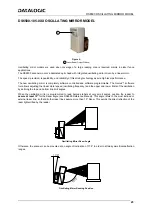
Page 25: ...oftware tool allows adjusting the linear motor speed oscillating frequency and the upper and lower limits of the oscillation by defining the top and bottom line limit angles When the oscillating mirro...

Page 26: ...10 30 11 15 20 16 19 10 NOTE By limiting the raster width to the minimum necessary the number of scans on the reading surface is increased 24 Oscillating angles are selected in software where the mini...

Page 27: ...sitive for Encoder 30 IN 2 ENC B polarity insensitive for Encoder 31 33 IN 3A polarity insensitive 32 34 IN 4A polarity insensitive 36 IN 3B IN 4B Reference polarity insensitive Outputs 21 OUT 1 22 OU...

Page 28: ...ning them about half way 5 completely tighten the two screws on top of the head 6 completely tighten the four fixing screws Step A Head Feature 4 33 4 45 110 113 99 3 90 76 30 74 2 99 1 18 2 85 85 16...

Page 29: ...uaranteed that the scanner reading performances see reading diagram section will match those measured for the standard installation with Skew angle between 10 20 NOTE The ST 210 mounting bracket is an...

Page 30: ...1 1 5 2 2 5 3 0 25 8 9 11 13 15 17 5 7 8 10 11 13 0 30 8 10 12 14 16 18 6 7 9 10 12 13 0 33 9 11 13 14 16 18 6 8 9 11 12 14 0 38 10 11 13 15 17 19 7 8 10 11 13 14 0 50 12 13 15 17 19 21 8 9 11 12 14...

Page 31: ...40 50 cm 60 20 24 80 32 in cm 0 10 20 30 8 12 4 0 40 16 50 20 10 4 20 8 0 25 mm 10 mils 0 3 mm 12 mils 90 36 100 40 70 28 40 16 50 20 30 12 0 375 mm 15 mils DS6500 105 0XX CONDITIONS Code Interleaved...

Page 32: ...0 15 30 45 12 18 6 0 60 24 75 30 15 6 30 12 0 5 mm 20 mils 155 62 170 68 125 50 60 24 75 30 45 18 0 375 mm 15 mils DS6500 205 0XX CONDITIONS Code Interleaved 2 5 or Code 39 PCS 0 90 Pitch angle 0 Skew...

Page 33: ...RTS 8 CTS 5 CTS How To Build A Simple Interface Test Cable The following wiring diagram shows a simple test cable including power external push button trigger and PC RS232 COM port connections 25 pin...

Page 34: ...correct scanning speed The laser beam can be switched off through a software command see also the Genius Help On Line AVOID EXPOSURE LASER RADIATION IS EMITTED FROM THIS APERTURE AVOID EXPOSURE LASER...

Page 35: ...O BEAM CLASS 3B LASER PRODUCT MAXIMUM OUTPUT RADIATION 35 mW EMITTED WAVE LENGTH 630 680 nm TO EN60825 1 2001 Laser Diode Class Label Any violation of the optic parts in particular can cause radiation...

Page 36: ...product safety Bas e sur la l gislation des Etats membres relative la compatibilit lectromagn tique et la s curit des produits ber die Ann herung der Gesetze der Mitgliedsstaaten in bezug auf elektro...

Reviews: