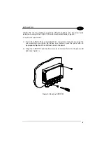
background image

C-BOX 100 


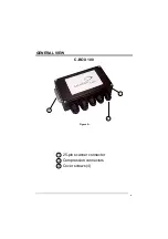
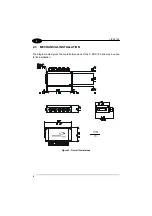
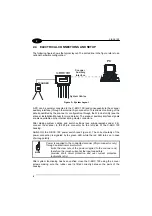
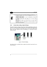
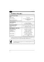
2.4  ELECTRICAL CONNECTIONS AND SETUP 

 
The following figure shows the typical layout. The dotted line in the figure refers to an 
optional hardware configuration. 
 

PC

SCANNER

System Cables

Scanner 

Auxiliary 

Interface

TX
 D

A

TA

EX
T

 T

R

IG

G

OOD

 R

E

A

D

PO
W

E

R

 O

N


Figure 5 – System Layout 

 
A PC can be quickly connected to the C-BOX 100 (and consequently to the scanner 
auxiliary interface) through the internal 9-pin connector. This allows monitoring of the 
data transmitted by the scanner or configuration through the WinHost utility (see the 
scanner Installation Manual for more details). The scanner auxiliary interface signals 
are also available on the internal spring clamp connectors. 


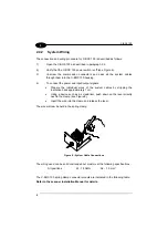
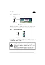
After making system cabling and switch settings (see sub-paragraphs under 2.4), 
connect the scanner to the 25-pin connector on the left side of the C-BOX 100 
housing. 


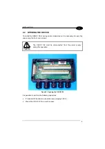
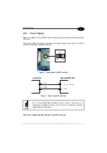
Switch ON the C-BOX 100 power switch (see Figure 6). The correct polarity of the 
power connection is signaled by the green LED, while the red LED turns on in case 
of wrong polarity. 


NOTE 

Power is supplied to the connected scanner (25-pin connector only) 
through an electronic circuit which: 

limits the slew rate of the power supplied to the scanner and, 
therefore, the inrush current at the input capacitors; 

provides short circuit protection and over current protection 
(automatic retry). 


After system functioning has been verified, close the C-BOX 100 using the 4 cover 
screws making sure the rubber seal is fitted correctly between the parts of the 
housing. 

Summary of Contents for C-BOX 100

Page 1: ...C BOX 100 Installation Manual...

Page 2: ...C BOX 100 Installation Manual...

Page 3: ...C BOX 100 INSTALLATION MANUAL...

Page 4: ...thout prior notification Datalogic shall not be liable for technical or editorial errors or omissions contained herein nor for incidental or consequential damages resulting from the use of this materi...

Page 5: ...ATION 2 2 1 Package Contents 2 2 2 Opening the Device 3 2 3 Mechanical Installation 4 2 4 Electrical Connections and Setup 6 2 4 1 Power Supply 7 2 4 2 System Wiring 8 2 4 3 Chassis Grounding Jumper S...

Page 6: ...ation in the section Safety Precautions at the beginning of this manual 2 Correctly position and mount the C BOX 100 within the reach of the barcode scanner cable according to the information in parag...

Page 7: ...v GENERAL VIEW C BOX 100 2 1 3 Figure A 25 pin scanner connector Cover screws 4 Compression connectors 1 2 3...

Page 8: ...is grounding selector 3 20 mA C L connector 5 4 Power on LED green Power Polarity Error LED red 6 Scanner selection switch Auxiliary port connector 7 OM4000 jumpers 8 Termination resistance switch 9 S...

Page 9: ...o be supplied by an NEC Class 2 power source rated 10 30 V minimum 0 50 A CAUTION The overall value of power consumption of the system C BOX 100 scanner is given by adding the scanner power consumptio...

Page 10: ...viii...

Page 11: ...vided through spring clamp terminal blocks inside the C BOX 100 The scanner is connected to the C BOX 100 through a 25 pin connector placed on the left side of the housing A 9 pin connector placed ins...

Page 12: ...KAGE CONTENTS Verify that the C BOX 100 and all the parts supplied with the equipment are present and intact when opening the packaging the list of parts includes 1 C BOX 100 2 Installation manual 1 2...

Page 13: ...to open it by unscrewing the four cover screws CAUTION The C BOX 100 must be disconnected from the power supply during this operation Figure 2 Opening the C BOX 100 It is possible to perform the follo...

Page 14: ...C BOX 100 4 2 2 3 MECHANICAL INSTALLATION The diagram below gives the overall dimensions of the C BOX 100 and may be used for its installation Figure 3 Overall Dimensions...

Page 15: ...gure 4 To mount the C BOX 100 1 Open the C BOX 100 by unscrewing the 4 cover screws If necessary using the two mounting holes inside the device as a pattern mark the panel with an appropriate object a...

Page 16: ...he internal spring clamp connectors After making system cabling and switch settings see sub paragraphs under 2 4 connect the scanner to the 25 pin connector on the left side of the C BOX 100 housing S...

Page 17: ...th the C BOX 100 and the connected scanner S1 ON OFF Figure 6 Power Switch ON OFF Positions C BOX 100 1 2 VS GND USER INTERFACE GND V 10 30 Vdc Figure 7 Power Supply Connections NOTE Pin 1 is also ele...

Page 18: ...e the individual wires of the system cables by stripping the insulation back approximately 1 cm Using a device such as a screwdriver push down on the lever directly next to the clamp see Figure 8 Inse...

Page 19: ...SA SGND AUX NC GND GND 39 SGND SGND SGND GND GND DS2100 DS2400 DS4300 DS4600 A DS6XXX MATRIX 2XXX DS1100 DS2200 MATRIX 1XXX RS232 RS485FD RS485HD 20mA CL RTX485HD 11 15 TX232 TX485 RTX485 CLOUT RTX485...

Page 20: ...rs SGND MAIN is internally connected to the GND through a filtering circuit 2 4 3 Chassis Grounding Jumper Settings The scanner chassis grounding method can be selected by positioning a jumper see Fig...

Page 21: ...esistance Switch The switch S2 enables or disables the insertion of the bus termination resistor for RS485 Half Duplex Multidrop applications CAUTION In Multiplexer applications the termination resist...

Page 22: ...terminals for applications which use the OM4000 Oscillating Mirror in Trigger Mode They are used together and have the following significance when a jumper is in the J1 position see Figure above pin 4...

Page 23: ...re indicated in the following table Figure 13 9 pin Male Connector 9 pin connector pinout Pin Name Function 1 N C 2 RXA Auxiliary RS232 3 TXA Auxiliary RS232 4 N C 5 SGND Signal Ground 6 N C 9 N C DS2...

Page 24: ...0 g 11 29 oz ENVIRONMENTAL FEATURES Operating temperature 10 to 50 C 14 to 122 F Storage temperature 20 to 70 C 4 to 158 F Humidity max 90 non condensing Vibration resistance IEC 68 2 6 test FC 1 5 mm...

Page 25: ...s of Member States relating to electromagnetic compatibility and product safety Bas e sur la l gislation des Etates membres relative la compatibilit lectromagn tique et la s curit des produits ber die...

Reviews: