background image

Rack Installation

96-30051-001 Rev. D3

DDN SFA12K (SFA OS 2.3.1) Hardware Installation & Configuration Guide | 48

5.

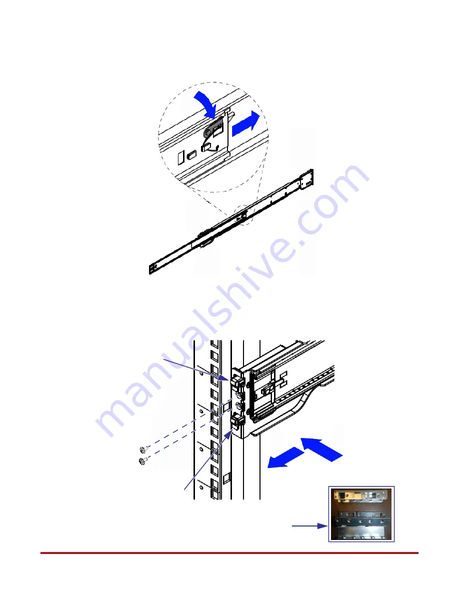
Press the locking tab and push the middle rail back into the outer rail

(Figure 54)

.

6.

Hang the hooks of the rail on the rack holes

(Figure 55)

Round hole adapters are

available for use on racks with round screw holes. Optional: Secure rail with two
screws.

Figure 54. Retract Middle Rail into Outer Rail 

1

2

Figure 55. Attach Rails to Rack 

1

2

Hook on Rail

Hook on Rail

Round Hole Adapters

Summary of Contents for SFA12K-20

Page 1: ...Hardware Installation Configuration Guide SFA12Ki SFA12KX SFA12K 40 SFA12K 20 SFA12KXE SFA12K 20E SFA12K Series SFA OS Version 2 3 1 96 30051 001 Revision D3 ...

Page 2: ...tion the implied warranties of merchantability and fitness for a particular purpose of any products or software DataDirect Networks does not warrant guarantee or make any representations regarding the use or the results of the use of any products or software in terms of correctness accuracy reliability or otherwise The entire risk as to the results and performance of the product and software are a...

Page 3: ... noted SFA12K 20 the block storage appliance SFA12KX 12K 40 the high performance block storage appliance twice the disk bandwidth performance of SFA12K 20 SFA12KXi the ultra high IOPS and bandwidth block storage appliance SFA12KXE 12K 20E the filesystem appliance model with embedded virtual machine support for DDN GRIDScaler and DDN EXAScaler scalable parallel file system solutions Refer to the SF...

Page 4: ...rface 23 8 2 Configure the Parameters 24 8 3 Other Recommended Configurations 26 8 4 Reconnect ATS 27 9 Powering On the System 28 9 1 Powering On using the Controller Power Button 30 10 Serial Interface Setup Accessing the CLUI 30 11 Configuring Network Interface Settings 31 11 1 Management Network Ports 31 11 2 Virtual Function Interface on E Platforms 31 11 3 Procedure 31 12 Starting the GUI Man...

Page 5: ...sks 39 19 3 Create and Assign Spare Pools 40 20 SFA12K Host Connections 41 21 Present Virtual Disks to External Hosts 41 21 1 Create a Host 41 21 2 Map Hosts to Discovered Initiators 42 21 3 Create the Presentation 42 Appendix A Rack Installation 44 A 1 Rackmounting the Controller 44 A 2 Rackmounting the Battery Backup Unit 52 A 3 Rackmounting the Automatic Transfer Switch 55 Appendix B Disk Enclo...

Page 6: ...age Parameters 25 Figure 18 Select Preferred Source 26 Figure 19 ATS Front Panel 26 Figure 20 Reconnect Power Cables from ATS with BBU Model 5P1550GR 27 Figure 21 Reconnect Power Cables to ATS with BBU Model 1550 27 Figure 22 ATS Front Panel 28 Figure 23 BBU Status LED Indicators on Front Panel Model 5P1550GR 28 Figure 24 BBU Front Panel 29 Figure 25 Controller Power Button and LEDs 29 Figure 26 R...

Page 7: ... Secure Front of Rail to Rack 53 Figure 68 Remove BBU Front Covers 54 Figure 69 Connect BBU Battery 54 Figure 70 ATS Rackmount Kit 55 Figure 71 BBU Alignment Washer and ATS Pan Head Screw 55 Figure 72 Attach Mounting Bracket to Rack Frame 55 Figure 73 Attach ATS to Brackets 56 Figure 74 Tighten Pan Head Screws 56 Figure 75 SFA12K 20 Configuration with 1 x SS7000 Enclosure 59 Figure 76 SFA12K 20 Co...

Page 8: ... with 1 x SS7000 Enclosure 87 Figure 104 SFA12KXE 12K 20E Configuration with 2 x SS7000 Enclosures 88 Figure 105 SFA12KXE 12K 20E Configuration with 3 x SS7000 Enclosures 89 Figure 106 SFA12KXE 12K 20E Configuration with 4 x SS7000 Enclosures 90 Figure 107 SFA12KXE 12K 20E Configuration with 5 x SS7000 Enclosures 91 Figure 108 SFA12KXE 12K 20E Configuration with 10 x SS7000 Enclosures 92 Figure 10...

Page 9: ...5 For block storage configurations create storage pools virtual disks spare pools and presentations Sections 16 to 21 2 Unpacking the System If your system is already installed in the racks refer to the DDN 42U 45U 28 Wide Rack Installation and Service Guide for instructions on removing the system from the shipping crate and positioning the system Before you unpack your SFA12K inspect the shipping...

Page 10: ... Installation and Service Guide for additional information on safety requirements 3 Rack Installation Refer to Appendix A for instructions on how to install a SFA12K controller BBU and ATS into a rack Refer to the StorageScaler 7000 User Guide for instructions on how to install the SS7000 disk enclosures and cable management hardware into a rack Refer to the StorageScaler 8460 User Guide for instr...

Page 11: ...mong the disk enclosures Always fill the rows from front to back also see Section 5 1 for blank module requirements Place disks with similar rotational speed in the same row If a mixture of disk technologies will be populated into one enclosure for optimal cooling the best loading order from front to back will be 10 000 RPM disks 7 200 RPM disks then SSD 3 5 HDD then 2 5 HDD or smaller Figure 1 an...

Page 12: ...f your system is already installed in the racks there are four shipping screws installed on the front panel of each disk enclosure to secure them for transit These screws must be removed or loosened before the enclosure can be pulled out for disk module installation For SS8460 enclosures remove the four shipping screws as shown in Figure 3 For SS7000 enclosures loosen the four shipping screws as s...

Page 13: ... pulling until the enclosure locks and you hear a clicking sound 2 Open the enclosure covers 3 Release the handle on the disk module 4 Insert the module into a disk bay Cam the disk module home The camming foot on the base of the module will engage into the slot in the enclosure 5 When the module is fully inserted close the handle 6 After you have installed all the disk modules and blank modules i...

Page 14: ...en the controller and its BBU as shown 4 For each ATS connect the power cable to its BBU as shown 5 Attach a power cord retainer included in the accessory kit to each of the power supply on the controllers as shown in Figure 5 Secure the power cord with the retainer Table 1 Controller Cabling Figures Configuration with BBU Model 5P1500GR Reference Configuration with BBU Model 1550 Reference SFA12K...

Page 15: ...ware Installation Configuration Guide 15 Controller 1 s BBU Model 5P1550GR Controller 0 Controller 0 s BBU Controller 1 Controller 0 s ATS Controller 1 s ATS Figure 6 Connecting SFA12K 20 Controllers to ATSs and BBU Model 5P1550GR Model 5P1550GR InfiniBand cable AC power cable USB cable ...

Page 16: ...1 Hardware Installation Configuration Guide 16 Controller 0 Figure 7 Connecting SFA12K 20 Controllers to ATSs and BBU Model 1550 Controller 0 s BBU Controller 1 s BBU Controller 0 s ATS Controller 1 s ATS Controller 1 Model 1550 Model 1550 InfiniBand cable AC power cable USB cable ...

Page 17: ...Installation Configuration Guide 17 Controller 1 s BBU Model 5P1550GR Controller 0 s BBU Model 5P1550GR Controller 1 Controller 0 Controller 0 s ATS Controller 1 s ATS Figure 8 Connecting SFA12KXi 12KX 12K 40 Controllers to ATSs and BBU Model 5P1550GR InfiniBand cable AC power cable USB cable ...

Page 18: ...dware Installation Configuration Guide 18 Controller 1 Figure 9 Connecting SFA12KXi 12KX 12K 40 Controllers to ATS and BBU Model 1550 Controller 0 Controller 0 s BBU Controller 1 s BBU Controller 0 s ATS Controller 1 s ATS Model 1550 Model 1550 InfiniBand cable AC power cable USB cable ...

Page 19: ... Installation Configuration Guide 19 Controller 1 s BBU Model 5P1550GR Controller 0 s BBU Model 5P1550GR Controller 1 Figure 10 Connecting SFA12KXE 12K 20E Controllers to ATSs and BBU Model 5P1500GR Controller 0 Controller 0 s ATS Controller 1 s ATS InfiniBand cable AC power cable USB cable ...

Page 20: ...rdware Installation Configuration Guide 20 Controller 0 Controller 1 Figure 11 Connecting SFA12KXE 12K 20E Controllers to ATSs and BBU Model 1550 Controller 0 s BBU Controller 1 s BBU Controller 0 s ATS Controller 1 s ATS Model 1550 Model 1550 InfiniBand cable AC power cable USB cable ...

Page 21: ...ectors to the PDUs It is recommended to connect the ATS Source A to the PDUs on the left side when viewed from the back of the rack and connect Source B to the PDUs on the right side 3 Connect the disk enclosures power supplies to the PDUs 4 Connect the PDUs to your AC power source For maximum redundancy connect the PDUs to different AC circuits Figure 12 illustrates an example for the PDU wiring ...

Page 22: ...DN SFA12K SFA OS 2 3 1 Hardware Installation Configuration Guide 22 Figure 12 Example of PDU Wiring in Rack Rear View ATS BBU Controller 0 BBU ATS Controller 1 Disk Enclosure Disk Enclosure Disk Enclosure Disk Enclosure Disk Enclosure PDU Source A PDU Source B ...

Page 23: ...rrent network interface settings on the ATS NOTE It is recommended that the ATS remains disconnected from any management networks after initial setup unless you plan on monitoring it with event notifications as outlined in the SFA OS User Guide 1 Temporarily unplug the controllers and BBUs power cables from the ATSs as shown in Figure 13 and Figure 14 To ensure that the BBUs and controllers remain...

Page 24: ...ternet Explorer IE 5 5 or higher on Windows operating systems 7 Enter the user name and password The default administrator user name is apc and password is apc Note that entries are case sensitive If you are unable to connect to the ATS Web interface check the Ethernet cabling and retry 8 2 Configure the Parameters You must configure these parameters according to the nominal AC voltage at your sit...

Page 25: ...ted For example using the data in Figure 16 Source A Voltage 249 Source B Voltage 240 Average AC Line voltage 249 240 2 244 5 Nominal AC line voltage 240 because that is the closest number to 244 5 from the list Note Use this value when setting the BBUs nominal voltage as described later in Section 13 4 Set the ATS Line VRMS Go to Unit tab Select Configuration Frequency voltage Figure 17 Figure 16...

Page 26: ...preferred source Go to Unit tab Select Configuration source Figure 18 In the Preferred Source field select None Click Apply to save the changes 6 Verify that the Input A and B LEDs are both illuminated on the front panel Figure 19 7 Repeat steps 1 to 6 above on the other ATS 8 3 Other Recommended Configurations You may configure the date and time administrator user name and password and event noti...

Page 27: ... the controllers and BBUs 1 Turn off the ATSs by turning off the PDUs 2 Reconnect the power cords between the units as shown in Figure 20 and Figure 21 Figure 20 Reconnect Power Cables from ATS with BBU Model 5P1550GR Reconnect these two power connectors BBU Model 5P1550GR Controller ATS Figure 21 Reconnect Power Cables to ATS with BBU Model 1550 BBU ATS Controller Model 1550 Reconnect these two p...

Page 28: ...h ATSs Figure 22 Verify that the unit displays 0 on the front panel indicating that it is ready Verify that both Input A and B LEDs are ON indicating that the ATS is operating with full source redundancy Verify that the Output LED is ON indicating that output voltage is available 4 Turn on both BBUs For systems using Model 5P1550GR go to step 5 For systems using Model 1550 go to step 6 5 On both B...

Page 29: ... ON check the power input to the BBU Verify that both Load Segment 1 and Load Segment 2 LEDs turn ON after 13 seconds 7 Turn on both controllers Remove the controller front bezel Press the power button once Figure 25 Reinstall the front bezel 8 On both controllers Figure 25 Verify that the Power indicator is green The PSU Fault LED turns on during power up Verify that it turns off after 13 seconds...

Page 30: ...ernet connection it is first necessary to configure the network settings on each controller This can only be done using the serial interface as described in Section 11 The RS 232 console can also be used to log the console output and to upgrade the BIOS BMC firmware 1 Connect a null modem cable between a PC and the RS 232 connector on the back of the controller Figure 26 2 On the RS 232 console lo...

Page 31: ...thernet interfaces on the SFA12KXE 12K 20E controller support SR IOV Single Root I O Virtualization which allows you to bind a virtual function interface associated with the SFA controller s own Ethernet interface to each virtual machine This gives your VM a direct easy to manage physical presence on your network that does not disrupt the data network The standard configuration is to connect the c...

Page 32: ...k 255 255 240 0 inet6 addr fe80 201 ffff fe0a 4f5 64 Scope Link UP BROADCAST RUNNING MULTICAST MTU 1500 Metric 1 RX packets 451807 errors 0 dropped 1039 overruns 0 frame 0 TX packets 51763 errors 0 dropped 0 overruns 0 carrier 0 collisions 0 txqueuelen 1000 RX bytes 667909491 636 9 MiB TX bytes 5584791 5 3 MiB Interrupt 18 Memory faf00000 faf20000 IP Routing Table Destination Gateway Genmask Flags...

Page 33: ...d see an alert message below the Health Indicator which shows that manual intervention is required for both controllers For E platforms with storage pre configured the Health indicator should be green 3 Click on the alert message Figure 30 4 At the Show Controller screen select the underlined Manual Intervention Required Details of the MIR state displays STATUS MIR no quorum disks found 5 Click CL...

Page 34: ...ce Then enter the MARK SUBSYSTEM TEXT command For example MARK SUBSYSTEM TEXT MAIN CTLR 0 BBU BAT SET TO 2014 09 13 Mark the log for both BBUs 14 Subsystem Configuration 14 1 Verify Physical Disk Status Select Physical Disks Show Physical Disks Verify that all the disks are present and healthy If the disks are not visible refer to the SFA OS User Guide for troubleshooting information 14 2 Set Subs...

Page 35: ...rs in any order Each controller name needs to be unique in the subsystem 3 Click Update to save the changes 15 Accessing the Virtual Machines on E Platforms The SFA12KXE 12K 20E initial subsystem configuration is complete at this point The procedures given in the rest of this document can be skipped Refer to the SFA OS User Guide Accessing VMs on SFA12KXE 12K 20E for information on accessing the v...

Page 36: ...on Figure 36 Host Ports on SFA12K 20 Controller InfiniBand Option Figure 37 Host Ports on SFA12K 20 Controller Dual Port FC 16 Option 0 3 2 1 1 0 3 2 Figure 33 Host Ports on SFA12KXi 12KX 12K 40 Controller InfiniBand Option RP0 Host Ports RP1 Host Ports RP0 Host Ports 0 1 2 3 4 5 6 7 4 5 6 7 0 1 2 3 Figure 34 Host Ports on SFA12KXi 12KX Controller Quad Port FC 16 Option RP0 Host Ports RP1 Host Por...

Page 37: ...d in the SED Default Password document attached to the enclosure covers Please refer to Section 20 and Section 21 for information on connecting your hosts and configuring presentations 18 Encryption Policy Setting SFA12K supports encryption capable disks If you have purchased the SED Self Encrypting Drives management license refer to Appendix D for instructions on how to generate the activation ke...

Page 38: ...irtual disk of 10 GiB Figure 38 illustrates the disk channels that are served by RP0 and RP1 on the SFA12K controllers 19 1 Create Storage Pools NOTE It is NOT recommended to configure storage pools with physical disks of different capacity as the SFA12K will use the lowest capacity for all disks and space will be wasted 1 Select Pools Create Storage The Create Storage Pool screen displays Figure ...

Page 39: ...nded that you select the DirectProtect method at the time of pool creation Also refer to the SFA OS User Guide for additional information on all the pool attributes which may also be changed later Select Pools Set Storage Attributes Figure 40 Change the settings for each pool Click UPDATE to save the changes 19 2 Create Virtual Disks A virtual disk can span a portion or utilize the entire capacity...

Page 40: ...ol contains physical disks that can be used as spare disks in one or more storage pools Up to 32 spare pools are supported Spare pools can be shared by storage pools or dedicated to a particular storage pool in which case the spare disks will only be used by the designated storage pool 1 Select Pools Create Spare The Create Spare Pool screen displays Figure 42 2 Similar to storage pool creation yo...

Page 41: ... Section 16 for host port locations 21 Present Virtual Disks to External Hosts NOTE For E platforms the feature to present virtual disks to external hosts is not applicable Virtual disks are only presented to the hosts that have been given authorized access The following sections describe how to present a virtual disk to an external host 21 1 Create a Host 1 Select Application Create Host 2 Select...

Page 42: ...isplays Figure 45 2 Select the initiator 3 Select the corresponding hosts 4 Click Import Initiator Success or error message displays 5 Repeat the above steps to create other host to initiator mappings as needed 21 3 Create the Presentation 1 Select Application Create Presentation 2 At the Create Presentation screen Figure 46 select a host Figure 45 Application Import Initiator Screen Figure 46 App...

Page 43: ...ly pathed through and if the host connection is lost access to that VD is also lost LUN LUN that the virtual disk will show to the host Channels from which host port the host will see the virtual disk 5 If desired enter an index number for the presentation 6 Click Create Presentation Success or error message displays 7 Repeat the above steps to create more presentations as needed To view the new p...

Page 44: ...types of controller rail The standard rail which ships with the product is designed for use with racks with vertical post separation distance of 26 75 and greater Figure 47 An optional short rail kit is available for racks where the vertical post separation is 26 75 or less The SFA12K family controllers are designed to fit within a 3U rack space Figure 48 illustrates the position of the rail and c...

Page 45: ...e flanges to the two sides of the controllers using six screws Figure 50 CAUTION The main purpose of the chassis handles is for rackmount use only Do NOT lift carry or transport the controller by the handles 2 Pull the inner rail out of the outer rail until it is fully extended Figure 51 Then press the locking tab down to release the inner rail Repeat for the other set of rails Figure 49 Controlle...

Page 46: ...Rack Installation 96 30051 001 Rev D3 DDN SFA12K SFA OS 2 3 1 Hardware Installation Configuration Guide 46 Figure 51 Release Inner Rail Pull Inner Rail Out Locking Tab Outer Rail Middle Rail Inner Rail ...

Page 47: ...nner rail with the hooks on the chassis Slide the inner rail forward until it clicks into the locked position NOTE The left and right rails differ from each other Do not exchange the inner rails 4 Use a short flat head screw to secure the inner rail to chassis Figure 53 Figure 52 Attach Inner Rails to Chassis RIGHT LEFT 1 2 Figure 53 Attach Inner Rails to Chassis Screw Location Standard Rail Short...

Page 48: ...middle rail back into the outer rail Figure 54 6 Hang the hooks of the rail on the rack holes Figure 55 Round hole adapters are available for use on racks with round screw holes Optional Secure rail with two screws Figure 54 Retract Middle Rail into Outer Rail 1 2 Figure 55 Attach Rails to Rack 1 2 Hook on Rail Hook on Rail Round Hole Adapters ...

Page 49: ...onal Secure with two screws Similarly attach the other rail to rack 8 Pull the middle rail out of the front of the outer rail and make sure that the ball bearing shuttle is locked at the front of the middle rail Figure 57 NOTE Keep the ball bearing shuttle locked at the front of the middle rail during installation Figure 56 Rail Attached to Rack Figure 57 Install Chassis in Rack Ball Bearing Shutt...

Page 50: ...on both sides of the chassis until it clicks into the fully extended position Figure 57 NOTE Due to the weight of the controller a minimum of two people is required for safe installation of the chassis 11 Depress the locking tabs on the inner rails simultaneously and push the chassis all the way into the rack Figure 57 12 Secure the chassis to the front of the rack using the two long screws one on...

Page 51: ...he front bezel Figure 60 The bezel uses ball stud and clip fasteners Align the clips at each corner of the bezel Figure 61 with the ball studs on the flanges Figure 62 Push the bezel in until all four studs engage with the clips Figure 60 SFA12K Front Bezel Figure 61 Clip on Back of Bezel Figure 62 Ball Studs on Flanges ...

Page 52: ... washers Figure 63 Note that the power cord retainers are not used with the SFA12K Remote Power Connector Ensure that the remote power connector is securely attached to the back panel of the BBU as shown in Figure 64 otherwise the BBU will not function correctly A 2 1 Battery Manufacturing Date Note down the BBU s battery manufacturing date Figure 65 You will need to enter this date during initial...

Page 53: ...pth of your rack Figure 66 Use two screws and washers to attach the rear end Use one screw and washer at the bottom to attach the front 2 Attach the two mounting brackets to the two sides of the BBU using four flat head screws Figure 67 Note the orientation of the bracket as shown Figure 66 Attach Rack Rails to Rack Front of Rack Figure 67 Secure Front of Rail to Rack Screw Hole at Top of Bracket ...

Page 54: ...nnect the battery as shown in Section A 2 3 A 2 3 Connect Battery on Model 5P1550GR The BBUs are shipped with the batteries disconnected Follow these steps to connect the batteries 1 Remove the front covers from the unit Figure 68 2 Fasten the two connectors together Figure 69 Note that it is normal if you see a spark and hear a pop sound as you connect the battery 3 Replace the front covers Figur...

Page 55: ...1 Remove the four screws and alignment washers that hold the BBU slides to the rack s rear vertical mounting rails Keep the four alignment washers from the BBU but discard the BBU mounting screws The pan head mounting screws provided with the ATS will be used for the installation Figure 71 2 Place the alignment washers and pan head screws on the ATS brackets two sets on each bracket as shown in Fi...

Page 56: ...h the ATS to the two brackets using the four flat head screws two screws on each side as shown in Figure 73 4 Verify that the alignment washers are properly aligned and seated in the vertical mounting rails Figure 74 Then tighten all four pan head screws to secure the ATS brackets Figure 73 Attach ATS to Brackets Figure 74 Tighten Pan Head Screws ...

Page 57: ...ables Zoning configuration setting is also shown for each configuration For E platforms and pre configured systems also refer to Section C 2 Enclosure Labels for information on determining enclosure positions in rack Table 3 Disk Enclosure Cabling Figures Configuration Enclosure Model Number of Enclosures Reference SFA12K 20 SS7000 1 Figure 75 2 Figure 76 3 Figure 77 4 Figure 78 5 Figure 79 10 Fig...

Page 58: ... 4 Figure 99 5 Figure 100 10 Figure 101 20 Figure 102 SFA12KXE SFA12K 20E SS7000 1 Figure 103 2 Figure 104 3 Figure 105 4 Figure 106 5 Figure 107 10 Figure 108 20 Figure 109 SS8460 1 Figure 110 2 Figure 111 3 Figure 112 4 Figure 113 5 Figure 114 10 Figure 115 20 Figure 116 Table 3 Disk Enclosure Cabling Figures Configuration Enclosure Model Number of Enclosures Reference ...

Page 59: ...Configuration Guide 59 Figure 75 SFA12K 20 Configuration with 1 x SS7000 Enclosure 012 002 012 002 112 102 I O Module A I O Module B Disk Enclosure 01 Controller 0 112 102 Controller 1 Zone 0 Zone 1 Zone 0 Zone 1 No of HD Mini SAS to Mini SAS Cables Required 3 meter 4 Zoning Configuration 1 ...

Page 60: ...gure 76 SFA12K 20 Configuration with 2 x SS7000 Enclosures 020 010 012 002 012 002 112 102 I O Module A I O Module B Disk Enclosure 01 Controller 0 120 110 112 102 Controller 1 020 010 120 110 I O Module A I O Module B Disk Enclosure 02 No of HD Mini SAS to Mini SAS Cables Required 3 meter 8 Zoning Configuration 1 ...

Page 61: ... x SS7000 Enclosures 020 022 010 012 000 002 012 002 112 102 I O Module A I O Module B Disk Enclosure 01 Controller 0 120 122 110 112 100 102 Controller 1 020 010 120 110 I O Module A I O Module B Disk Enclosure 02 022 000 122 100 I O Module A I O Module B Disk Enclosure 03 No of HD Mini SAS to Mini SAS Cables Required 3 meter 12 Zoning Configuration 1 ...

Page 62: ...12 000 001 002 012 002 112 102 I O Module A I O Module B Disk Enclosure 01 Controller 0 120 121 122 110 112 100 101 102 Controller 1 020 010 120 110 I O Module A I O Module B Disk Enclosure 02 022 000 122 100 I O Module A I O Module B Disk Enclosure 03 021 001 121 101 I O Module A I O Module B Disk Enclosure 04 No of HD Mini SAS to Mini SAS Cables Required 3 meter 16 Zoning Configuration 1 ...

Page 63: ... I O Module A I O Module B Disk Enclosure 01 Controller 0 120 121 122 110 112 113 100 101 102 103 Controller 1 020 010 120 110 I O Module A I O Module B Disk Enclosure 02 022 000 122 100 I O Module A I O Module B Disk Enclosure 03 021 001 121 101 I O Module A I O Module B Disk Enclosure 04 013 003 113 103 I O Module A I O Module B Disk Enclosure 05 No of HD Mini SAS to Mini SAS Cables Required 3 m...

Page 64: ... 03 020 120 I O Module A I O Module B Disk Enclosure 04 000 100 I O Module A I O Module B Disk Enclosure 05 022 122 I O Module A I O Module B Disk Enclosure 06 001 101 I O Module A I O Module B Disk Enclosure 07 021 121 I O Module A I O Module B Disk Enclosure 08 003 103 I O Module A I O Module B Disk Enclosure 09 013 113 I O Module A I O Module B Disk Enclosure 10 No of HD Mini SAS to Mini SAS Ca...

Page 65: ...e 10 065 022 165 122 I O Module A I O Module B Disk Enclosure 11 065 165 I O Module A I O Module B Disk Enclosure 12 066 001 166 101 I O Module A I O Module B Disk Enclosure 13 066 166 I O Module A I O Module B Disk Enclosure 14 067 021 167 121 I O Module A I O Module B Disk Enclosure 15 067 167 I O Module A I O Module B Disk Enclosure 16 068 003 168 103 I O Module A I O Module B Disk Enclosure 17...

Page 66: ...Installation Configuration Guide 66 Figure 82 SFA12K 20 Configuration with 1 SS8460 Enclosure 012 002 Controller 0 112 102 Controller 1 012 002 I O Module A Disk Enclosure 01 112 102 I O Module B No of HD Mini SAS to HD Mini SAS Cables Required 3 meter 4 Zoning Configuration 1 ...

Page 67: ...gure 83 SFA12K 20 Configuration with 2 SS8460 Enclosures 020 010 012 002 Controller 0 120 110 112 102 Controller 1 020 010 I O Module A Disk Enclosure 02 120 110 I O Module B 012 002 I O Module A Disk Enclosure 01 112 102 I O Module B No of HD Mini SAS to HD Mini SAS Cables Required 3 meter 8 Zoning Configuration 1 ...

Page 68: ... SS8460 Enclosure 020 022 010 012 000 002 Controller 0 120 122 110 112 100 102 Controller 1 022 000 I O Module A Disk Enclosure 03 122 100 I O Module B 020 010 I O Module A Disk Enclosure 02 120 110 I O Module B 012 002 I O Module A Disk Enclosure 01 112 102 I O Module B No of HD Mini SAS to HD Mini SAS Cables Required 3 meter 12 Zoning Configuration 1 ...

Page 69: ...000 001 002 Controller 0 120 121 122 110 112 100 101 102 Controller 1 021 001 I O Module A Disk Enclosure 04 121 101 I O Module B 022 000 I O Module A Disk Enclosure 03 122 100 I O Module B 020 010 I O Module A Disk Enclosure 02 120 110 I O Module B 012 002 I O Module A Disk Enclosure 01 112 102 I O Module B No of HD Mini SAS to HD Mini SAS Cables Required 3 meter 16 Zoning Configuration 1 ...

Page 70: ...121 122 110 112 113 100 101 102 103 Controller 1 013 003 I O Module A Disk Enclosure 05 113 103 I O Module B 021 001 I O Module A Disk Enclosure 04 121 101 I O Module B 022 000 I O Module A Disk Enclosure 03 122 100 I O Module B 020 010 I O Module A Disk Enclosure 02 120 110 I O Module B 012 002 I O Module A Disk Enclosure 01 112 102 I O Module B No of HD Mini SAS to HD Mini SAS Cables Required 3 ...

Page 71: ... Enclosure 10 113 I O Module B 003 I O Module A Disk Enclosure 09 103 I O Module B 021 I O Module A Disk Enclosure 08 121 I O Module B 001 I O Module A Disk Enclosure 07 101 I O Module B 020 021 022 010 012 013 000 001 002 003 Controller 0 120 121 122 110 112 113 100 101 102 103 Controller 1 Optional If you are using 3 meter cables only Remove side panels from the adjoining sides of racks Run cabl...

Page 72: ... 168 103 I O Module B 068 I O Module A Disk Enclosure 18 168 I O Module B 069 013 I O Module A Disk Enclosure 19 169 113 I O Module B 069 I O Module A Disk Enclosure 20 169 I O Module B 020 021 022 010 012 013 000 001 002 003 Controller 0 060 002 I O Module A Disk Enclosure 01 160 102 I O Module B 060 I O Module A Disk Enclosure 02 160 I O Module B 061 012 I O Module A Disk Enclosure 03 161 112 I ...

Page 73: ...guration Guide 73 Figure 89 SFA12KX 12K 40 Configuration with 1 x SS7000 Enclosure 012 002 042 032 012 002 142 132 112 102 I O Module A I O Module B Disk Enclosure 01 Controller 0 032 042 112 102 Controller 1 132 142 No of HD Mini SAS to Mini SAS Cables Required 3 meter 8 Zoning Configuration 1 ...

Page 74: ...n with 2 x SS7000 Enclosures 020 010 012 002 042 032 012 002 142 132 112 102 I O Module A I O Module B Disk Enclosure 01 Controller 0 050 040 020 010 150 140 120 110 I O Module A I O Module B Disk Enclosure 02 032 040 042 050 120 110 112 102 Controller 1 132 140 142 150 No of HD Mini SAS to Mini SAS Cables Required 3 meter 16 Zoning Configuration 1 ...

Page 75: ...42 032 012 002 142 132 112 102 I O Module A I O Module B Disk Enclosure 01 Controller 0 050 040 020 010 150 140 120 110 I O Module A I O Module B Disk Enclosure 02 052 030 022 000 152 130 122 100 I O Module A I O Module B Disk Enclosure 03 030 032 040 042 050 052 120 122 110 112 100 102 Controller 1 130 132 140 142 150 152 No of HD Mini SAS to Mini SAS Cables Required 3 meter 24 Zoning Configurati...

Page 76: ...O Module B Disk Enclosure 01 Controller 0 050 040 020 010 150 140 120 110 I O Module A I O Module B Disk Enclosure 02 052 030 022 000 152 130 122 100 I O Module A I O Module B Disk Enclosure 03 051 031 021 001 151 131 121 101 I O Module A I O Module B Disk Enclosure 04 030 031 032 040 042 050 051 052 120 121 122 110 112 100 101 102 Controller 1 130 131 132 140 142 150 151 152 No of HD Mini SAS to ...

Page 77: ...040 020 010 150 140 120 110 I O Module A I O Module B Disk Enclosure 02 052 030 022 000 152 130 122 100 I O Module A I O Module B Disk Enclosure 03 051 031 021 001 151 131 121 101 I O Module A I O Module B Disk Enclosure 04 043 033 013 003 143 133 113 103 I O Module A I O Module B Disk Enclosure 05 030 031 032 033 040 042 043 050 051 052 120 121 122 110 112 113 100 101 102 103 Controller 1 130 131...

Page 78: ...sure 05 052 022 152 122 I O Module A I O Module B Disk Enclosure 06 031 001 131 101 I O Module A I O Module B Disk Enclosure 07 051 021 151 121 I O Module A I O Module B Disk Enclosure 08 033 003 133 103 I O Module A I O Module B Disk Enclosure 09 043 013 143 113 I O Module A I O Module B Disk Enclosure 10 020 021 022 010 012 013 000 001 002 003 Controller 0 030 031 032 033 040 042 043 050 051 052...

Page 79: ... O Module A I O Module B Disk Enclosure 11 075 065 175 165 I O Module A I O Module B Disk Enclosure 12 076 031 066 001 176 131 166 101 I O Module A I O Module B Disk Enclosure 13 076 066 176 166 I O Module A I O Module B Disk Enclosure 14 077 051 067 021 177 151 167 121 I O Module A I O Module B Disk Enclosure 15 077 067 177 167 I O Module A I O Module B Disk Enclosure 16 078 033 068 003 178 133 1...

Page 80: ...iguration Guide 80 Figure 96 SFA12KX 12K 40 Configuration with 1 SS8460 Enclosure 042 032 012 002 I O Module A Disk Enclosure 01 142 132 112 102 I O Module B 112 102 Controller 1 012 002 Controller 0 042 032 142 132 No of HD MiniSAS to HD MiniSAS Cables Required 3 meter 8 Zoning Configuration 1 ...

Page 81: ...on with 2 SS8460 Enclosures 050 040 020 010 I O Module A Disk Enclosure 02 150 140 120 110 I O Module B 042 032 012 002 I O Module A Disk Enclosure 01 142 132 112 102 I O Module B 120 110 112 102 Controller 1 020 010 012 002 Controller 0 050 040 042 032 150 140 142 132 No of HD MiniSAS to HD MiniSAS Cables Required 3 meter 16 Zoning Configuration 1 ...

Page 82: ... A Disk Enclosure 03 152 130 122 100 I O Module B 050 040 020 010 I O Module A Disk Enclosure 02 150 140 120 110 I O Module B 042 032 012 002 I O Module A Disk Enclosure 01 142 132 112 102 I O Module B 120 122 110 112 100 102 Controller 1 020 022 010 012 000 002 Controller 0 050 052 040 042 030 032 150 152 140 142 130 132 No of HD MiniSAS to HD MiniSAS Cables Required 3 meter 24 Zoning Configurati...

Page 83: ...030 022 000 I O Module A Disk Enclosure 03 152 130 122 100 I O Module B 050 040 020 010 I O Module A Disk Enclosure 02 150 140 120 110 I O Module B 042 032 012 002 I O Module A Disk Enclosure 01 142 132 112 102 I O Module B 120 121 122 110 112 100 101 102 Controller 1 020 021 022 010 012 000 001 002 Controller 0 050 051 052 040 042 030 031 032 150 151 152 140 142 130 131 132 No of HD MiniSAS to HD...

Page 84: ...121 101 I O Module B 052 030 022 000 I O Module A Disk Enclosure 03 152 130 122 100 I O Module B 050 040 020 010 I O Module A Disk Enclosure 02 150 140 120 110 I O Module B 042 032 012 002 I O Module A Disk Enclosure 01 142 132 112 102 I O Module B 120 121 122 110 112 113 100 101 102 103 Controller 1 020 021 022 010 012 013 000 001 002 003 Controller 0 050 051 052 040 042 043 030 031 032 033 150 1...

Page 85: ... Module B 033 003 I O Module A Disk Enclosure 09 133 103 I O Module B 051 021 I O Module A Disk Enclosure 08 151 121 I O Module B 031 001 I O Module A Disk Enclosure 07 131 101 I O Module B 020 021 022 010 012 013 000 001 002 003 Controller 0 120 121 122 110 112 113 100 101 102 103 Controller 1 050 051 052 040 042 043 030 031 032 033 150 151 152 140 142 143 130 131 132 133 Optional If you are usin...

Page 86: ...e A Disk Enclosure 20 179 169 I O Module B 020 021 022 010 012 013 000 001 002 003 Controller 0 070 032 060 002 I O Module A Disk Enclosure 01 170 132 160 102 I O Module B 070 060 I O Module A Disk Enclosure 02 170 160 I O Module B 071 042 061 012 I O Module A Disk Enclosure 03 171 142 161 112 I O Module B 071 061 I O Module A Disk Enclosure 04 171 161 I O Module B 072 040 062 010 I O Module A Dis...

Page 87: ...tallation Configuration Guide 87 Figure 103 SFA12KXE 12K 20E Configuration with 1 x SS7000 Enclosure 012 002 012 002 112 102 I O Module A I O Module B Disk Enclosure 01 Controller 0 112 102 Controller 1 No of HD Mini SAS to Mini SAS Cables Required 3 meter 4 Zoning Configuration 1 ...

Page 88: ... 104 SFA12KXE 12K 20E Configuration with 2 x SS7000 Enclosures 020 010 012 002 012 002 112 102 I O Module A I O Module B Disk Enclosure 01 Controller 0 120 110 112 102 Controller 1 020 010 120 110 I O Module A I O Module B Disk Enclosure 02 No of HD Mini SAS to Mini SAS Cables Required 3 meter 8 Zoning Configuration 1 ...

Page 89: ...th 3 x SS7000 Enclosures 020 022 010 012 000 002 012 002 112 102 I O Module A I O Module B Disk Enclosure 01 Controller 0 120 122 110 112 100 102 Controller 1 020 010 120 110 I O Module A I O Module B Disk Enclosure 02 022 000 122 100 I O Module A I O Module B Disk Enclosure 03 No of HD Mini SAS to Mini SAS Cables Required 3 meter 12 Zoning Configuration 1 ...

Page 90: ...10 012 000 001 002 012 002 112 102 I O Module A I O Module B Disk Enclosure 01 Controller 0 120 121 122 110 112 100 101 102 Controller 1 020 010 120 110 I O Module A I O Module B Disk Enclosure 02 022 000 122 100 I O Module A I O Module B Disk Enclosure 03 021 001 121 101 I O Module A I O Module B Disk Enclosure 04 No of HD Mini SAS to Mini SAS Cables Required 3 meter 16 Zoning Configuration 1 ...

Page 91: ... 102 I O Module A I O Module B Disk Enclosure 01 Controller 0 120 121 122 110 112 113 100 101 102 103 Controller 1 020 010 120 110 I O Module A I O Module B Disk Enclosure 02 022 000 122 100 I O Module A I O Module B Disk Enclosure 03 021 001 121 101 I O Module A I O Module B Disk Enclosure 04 013 003 113 103 I O Module A I O Module B Disk Enclosure 05 No of HD Mini SAS to Mini SAS Cables Required...

Page 92: ...010 110 I O Module A I O Module B Disk Enclosure 03 020 120 I O Module A I O Module B Disk Enclosure 04 000 100 I O Module A I O Module B Disk Enclosure 05 022 122 I O Module A I O Module B Disk Enclosure 06 001 101 I O Module A I O Module B Disk Enclosure 07 021 121 I O Module A I O Module B Disk Enclosure 08 003 103 I O Module A I O Module B Disk Enclosure 09 013 113 I O Module A I O Module B Di...

Page 93: ...osure 10 065 022 165 122 I O Module A I O Module B Disk Enclosure 11 065 165 I O Module A I O Module B Disk Enclosure 12 066 001 166 101 I O Module A I O Module B Disk Enclosure 13 066 166 I O Module A I O Module B Disk Enclosure 14 067 021 167 121 I O Module A I O Module B Disk Enclosure 15 067 167 I O Module A I O Module B Disk Enclosure 16 068 003 168 103 I O Module A I O Module B Disk Enclosur...

Page 94: ...llation Configuration Guide 94 Figure 110 SFA12KXE 12K 20E Configuration with 1 x SS8460 Enclosure 012 002 Controller 0 112 102 Controller 1 012 002 I O Module A Disk Enclosure 01 112 102 I O Module B No of HD Mini SAS to HD Mini SAS Cables Required 3 meter 4 Zoning Configuration 1 ...

Page 95: ...e 111 SFA12KXE 12K 20E Configuration with 2 SS8460 Enclosures 020 010 012 002 Controller 0 120 110 112 102 Controller 1 020 010 I O Module A Disk Enclosure 02 120 110 I O Module B 012 002 I O Module A Disk Enclosure 01 112 102 I O Module B No of HD MiniSAS to HD MiniSAS Cables Required 3 meter 8 Zoning Configuration 1 ...

Page 96: ...th 3 SS8460 Enclosures 020 022 010 012 000 002 Controller 0 120 122 110 112 100 102 Controller 1 022 000 I O Module A Disk Enclosure 03 122 100 I O Module B 020 010 I O Module A Disk Enclosure 02 120 110 I O Module B 012 002 I O Module A Disk Enclosure 01 112 102 I O Module B No of HD MiniSAS to HD MiniSAS Cables Required 3 meter 12 Zoning Configuration 1 ...

Page 97: ... 012 000 001 002 Controller 0 120 121 122 110 112 100 101 102 Controller 1 021 001 I O Module A Disk Enclosure 04 121 101 I O Module B 022 000 I O Module A Disk Enclosure 03 122 100 I O Module B 020 010 I O Module A Disk Enclosure 02 120 110 I O Module B 012 002 I O Module A Disk Enclosure 01 112 102 I O Module B No of HD MiniSAS to HD MiniSAS Cables Required 3 meter 16 Zoning Configuration 1 ...

Page 98: ... 110 112 113 100 101 102 103 Controller 1 013 003 I O Module A Disk Enclosure 05 113 103 I O Module B 021 001 I O Module A Disk Enclosure 04 121 101 I O Module B 022 000 I O Module A Disk Enclosure 03 122 100 I O Module B 020 010 I O Module A Disk Enclosure 02 120 110 I O Module B 012 002 I O Module A Disk Enclosure 01 112 102 I O Module B Zone 1 Zone 2 No Zone No of HD Mini SAS to HD Mini SAS Cab...

Page 99: ...Disk Enclosure 10 113 I O Module B 003 I O Module A Disk Enclosure 09 103 I O Module B 021 I O Module A Disk Enclosure 08 121 I O Module B 001 I O Module A Disk Enclosure 07 101 I O Module B 020 021 022 010 012 013 000 001 002 003 Controller 0 120 121 122 110 112 113 100 101 102 103 Controller 1 Optional If you are using 3 meter cables only Remove side panels from the adjoining sides of racks Run ...

Page 100: ...e 17 168 103 I O Module B 068 I O Module A Disk Enclosure 18 168 I O Module B 069 013 I O Module A Disk Enclosure 19 169 113 I O Module B 069 I O Module A Disk Enclosure 20 169 I O Module B Controller 0 060 002 I O Module A Disk Enclosure 01 160 102 I O Module B 060 I O Module A Disk Enclosure 02 160 I O Module B 061 012 I O Module A Disk Enclosure 03 161 112 I O Module B 061 I O Module A Disk Enc...

Page 101: ...the module should be installed in For example ENCL 01 means the disk should be installed in the enclosure labeled ENCLOSURE 01 Refer to Section C 2 for more information on enclosure positions in rack The disk slot number indicates the disk s position within the enclosure Figure 118 and Figure 119 illustrate the slot numbering inside the 60 bay and 84 bay enclosures Figure 117 Pre Formatted Disk La...

Page 102: ...shows the enclosure positions for systems using up to 10 disk enclosures Figure 122 shows the enclosure positions for systems using 20 disk enclosures Figure 119 84 Bay Enclosure Disk Slot Numbering 01 15 29 43 57 02 16 30 44 58 03 17 31 45 59 04 18 32 46 60 05 19 33 47 61 06 20 34 48 62 71 72 73 74 75 76 07 21 35 49 63 08 22 36 50 64 09 23 37 51 65 10 24 38 52 66 11 25 39 53 67 12 26 40 54 68 77 ...

Page 103: ...ENCLOSURE 06 ENCLOSURE 07 ENCLOSURE 08 ENCLOSURE 09 ENCLOSURE 10 Controller 0 Controller 1 Figure 122 Enclosure Positions in Rack Front View ENCLOSURE 01 ENCLOSURE 02 ENCLOSURE 03 ENCLOSURE 04 ENCLOSURE 05 ENCLOSURE 11 ENCLOSURE 12 ENCLOSURE 13 ENCLOSURE 14 ENCLOSURE 15 Controller 0 Controller 1 ENCLOSURE 06 ENCLOSURE 07 ENCLOSURE 08 ENCLOSURE 09 ENCLOSURE 10 ENCLOSURE 16 ENCLOSURE 17 ENCLOSURE 18...

Page 104: ...rom the Controllers menu select Show Controllers Select to display the primary controller details Note down the controller ID 2 From the Enclosures menu select Show Enclosures Select to display the primary controller details usually at index 0 Note down the controller s baseboard serial number 3 Note down the 16 digit license number that came with your shipment 4 To generate an activation key go t...

Page 105: ...ctivation key is displayed if the license is activated successfully Note down this key You may save and or print a copy of the activation key 7 From the Subsystem menu select Set Subsystem Attributes Enter the license key and click Update Note that license activation may require a subsystem restart 8 From the Subsystem menu select Show Subsystem The subsystem details should show the feature has be...

Page 106: ...Corporate Headquarters 9351 Deering Avenue Chatsworth CA 91311 ddn com Phone 1 818 700 7600 Fax 1 818 700 7601 ...

Reviews: