


CR805 Retransfer Card Printer Instrallation and Administrator’s Guide
A-5
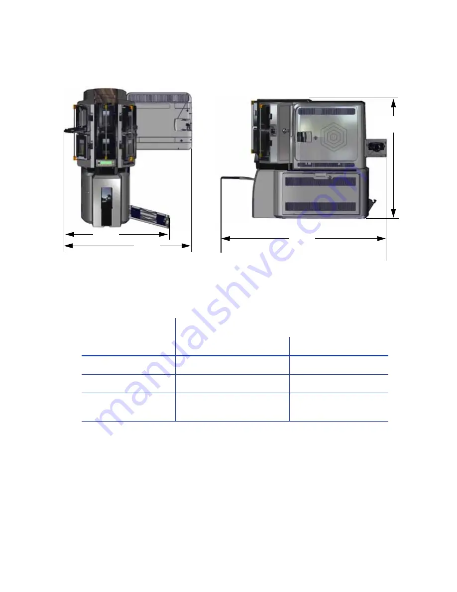
Multi-Hopper System
Electrical Requirements
The power supply is rated as follows:
System Component
Electrical Requirements
Input
Output
Printer
110–240V/50–60 Hz/1.5 Amp
24V/3.0Amp/72W
Laminator with L1 only
100–240V/47–63 Hz/2.2 Amp
24V/3.75Amp/90W
Laminator with L1, L2,
and impresser
100–240V/47–63 Hz/6.6 Amp
24V/6.6Amp/160W
28.8 in
732 mm
23.6 in
598 mm
38.2 in
970 mm
27.6 in
700 mm
Summary of Contents for CR805
Page 8: ...viii ...
Page 10: ...x ...
Page 16: ...xvi ...
Page 20: ...4 Printer Installation Multi Hopper Printer 13 4 in 340 mm 16 2 in 411 mm 25 6 in 651 mm ...
Page 28: ...12 Printer Installation Unpack the Optional Multi Hopper ...
Page 58: ...42 Printer Installation ...
Page 74: ...58 Elements of Card Design ...
Page 152: ...A 20 CLM Laminator ...


