Troubleshooting
91
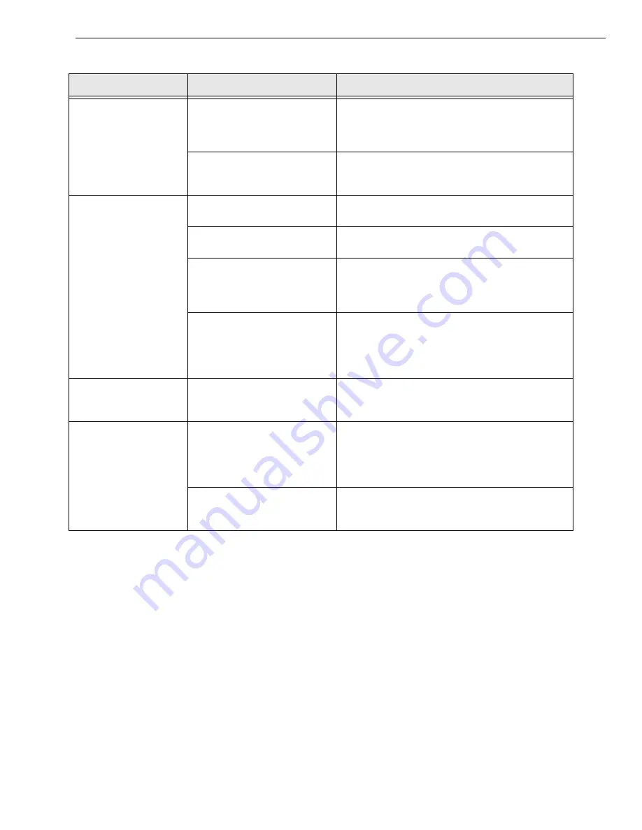
Device failure error
reported.
The module cannot
communicate with the Microsoft
bus driver or a problem with the
bus driver exists.
Check your cabling and wiring and tighten any loose
connections; see the instructions in
.
The module was removed while
an operation was being
performed.
Ensure that your module is properly connected; see
the instructions in
Data appears to be
invalid.
An open connection exists.
Check your wiring and fix any open connections; see
the instructions in
A transducer is not connected to
the channel being read.
Check the transducer connections; see the
instructions in
.
The transducer is set up for
differential inputs while the
module is wired for single-ended
inputs.
Check your wiring and ensure that your transducer
connects to the single-ended inputs of your module;
see the instructions in
The module is out of calibration.
The modules are calibrated at the factory. The
DT9812-2.5V does not require additional calibration.
If you want to readjust the calibration of any other
DT9812, DT9813, or DT9814 Series module, refer to
the instructions in
Computer does not boot.
The power supply of the
computer is too small to handle
all the system resources.
Check the power requirements of your system
resources and, if needed, get a larger power supply;
consult the module’s specifications on
.
USB 2.0 is not
recognized.
Your operating system does not
have the appropriate Service
Pack installed.
Ensure that you load the appropriate Windows
Service Pack (version 2 for Windows XP). If you are
unsure of whether you are using USB 2.0 or USB 1.1,
run the Open Layers Control Panel applet, described
in
Standby mode is enabled on
your PC.
For some PCs, you may need to disable standby
mode on your system for proper USB 2.0 operation.
Consult Microsoft for more information.
Table 22: Troubleshooting Problems (cont.)
Symptom
Possible Cause
Possible Solution
Summary of Contents for DT9812 Series
Page 1: ...DT9812 UM 20769 R DT9813 and User s Manual DT9814 Series Title Page ...
Page 4: ......
Page 12: ...About this Manual 12 ...
Page 13: ...13 1 Overview Key Hardware Features 14 Supported Software 15 Getting Started Procedure 16 ...
Page 17: ...Part 1 Getting Started ...
Page 18: ......
Page 26: ...Chapter 2 26 ...
Page 53: ...Part 2 Using Your Module ...
Page 54: ......
Page 76: ...Chapter 5 76 ...
Page 88: ...Chapter 6 88 ...
Page 94: ...Chapter 7 94 ...
Page 113: ...113 B Screw Terminal and Connector Pin Assignments ...


