


Chapter 2
24
For Windows XP:
a.
Click
Next
and/or
Finish
as required in the wizard.
Once the firmware is loaded, the wizard restarts to initiate the firmware to accept commands.
b.
Click
Next
and/or
Finish
again.
The LED on the module turns green.
Note:
Windows 7 finds the device automatically.
5.
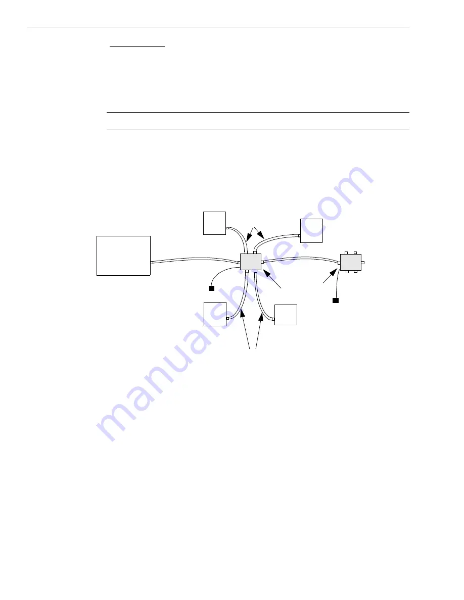
Repeat these steps until you have attached the number of expansion hubs (up to five) and
modules (up to four per hub) that you require. Refer to
The operating system automatically detects the USB devices as they are installed.
Figure 3: Attaching Multiple DT9812, DT9813, and/or DT9814 Series Modules
Using Expansion Hubs
USB Cable
Expansion Hubs
Host Computer
Power Supply
for Hub
USB Cables
USB Cables
USB Cable
Power Supply
for Hub
DT9812, DT9813, or
DT9814 Series Module
DT9812, DT9813, or
DT9814 Series Module
DT9812, DT9813, or
DT9814 Series Module
DT9812, DT9813, or
DT9814 Series Module
Summary of Contents for DT9812 Series
Page 1: ...DT9812 UM 20769 R DT9813 and User s Manual DT9814 Series Title Page ...
Page 4: ......
Page 12: ...About this Manual 12 ...
Page 13: ...13 1 Overview Key Hardware Features 14 Supported Software 15 Getting Started Procedure 16 ...
Page 17: ...Part 1 Getting Started ...
Page 18: ......
Page 26: ...Chapter 2 26 ...
Page 53: ...Part 2 Using Your Module ...
Page 54: ......
Page 76: ...Chapter 5 76 ...
Page 88: ...Chapter 6 88 ...
Page 94: ...Chapter 7 94 ...
Page 113: ...113 B Screw Terminal and Connector Pin Assignments ...


