


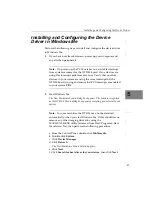


Chapter 4
26
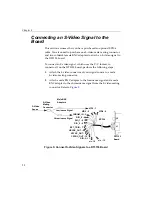
Connecting Multiple Composite Signals to the
Board
This section assumes that you have purchased an optional EP306
cable.
To connect multiple composite video signals, which use the
NTSC/RS-170 or PAL video format, to connector J1 on the DT3153
board, perform the following steps:
1.
After making sure power to the computer is off, push the 15-pin
connector of the EP306 cable into the J1 socket at the rear of the
DT3153, as shown in
, and tighten the screws on the
connector.
Figure 4: Connecting the EP306 Cable to Connector J1
CAUTION:
The single-use BNC input connector, J2, is shared with the VID0_IN
signal (pin 8) on video input connector J1. Do not attach signals to
both connectors; otherwise, the two video sources will be shorted
together, which could result in damage to the video sources.
J1
VID0 - 0
VID1 - 1
VID2 - 2
CHROM_IN - 3
DIO_0 - 4
DIO_1 - 5
DIO_2 - 6
EXT_TRIG - 7
EP306
HSYNC_OUT - 8
VSYNC_OUT - 9
CSYNC_OUT - 10
DIO-3 - 11
n/c -12
n/c - 13
J2
Summary of Contents for DT3153
Page 1: ...DT3153 UM 18227 D Getting Started Manual...
Page 8: ...About this Manual viii...
Page 9: ...1 1 Overview Key Hardware Features 2 DT3153 Software 3 Getting Started Procedure 4...
Page 24: ...Chapter 2 16...
Page 38: ...Chapter 4 30...
Page 54: ...Chapter 5 46...
Page 55: ...47 6 Verifying Board Operation Overview 49 Installing DT Acquire 50 Using DT Acquire 51...
Page 62: ...Chapter 6 54...


