Chapter 2
12
The following sections describe how to use the offset, gain, and
reference settings on the DT3152-LS board to adjust the black and
white levels of the video signal.
Offset
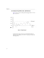
The offset is the voltage you apply to the minimum value (V
min
) of
your video signal to zero it. The offset is defined as follows:
offset =
−
V
min
All data below 0 V is digitized as black pixels.
The DT3152-LS Device Driver supports a minimum offset of
−
1.08 V
and a maximum offset of 1.07 V, in increments of 8.4 mV. Note,
however, that the hardware uses 64 steps of 33.6 mV.
For area-scan mode, the default offset is
−
53.86 mV for 60 Hz and 0 V
for 50 Hz. For line-scan mode, the default offset is 0 V.
Gain
Gain is the value you use to multiply the amplitude of the signal,
thereby increasing or decreasing the overall range of the signal. You
apply the gain after you apply the offset voltage. To maintain the
accuracy of the ADC at low light levels and to support a wider range
of video inputs, the DT3152-LS provides gains of 0.5, 1, 2, and 4. By
default, the gain is 1.
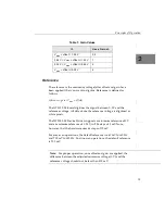
To determine the gain to use, calculate the maximum voltage of your
video signal after the offset is applied. Then, use the values in
to determine the gain to use.
Summary of Contents for DT3152-LS
Page 1: ...MACH Series UM 16481 F DT3152 LS User s Manual ...
Page 4: ......
Page 16: ...About this Manual xvi ...
Page 17: ...1 1 Overview Features 2 Supported Software 4 Accessories 6 ...
Page 142: ...Chapter 4 126 ...
Page 153: ...137 A Specifications ...
Page 156: ...Appendix A 140 ...
Page 162: ...Appendix B 146 ...
Page 192: ...Appendix C 176 ...
Page 193: ...177 D Asynchronous Reset Cameras ...
Page 196: ...Appendix D 180 ...
Page 210: ......
Page 214: ......


