Wiring Signals
59
5
5
5
5
5
5
5
5
5
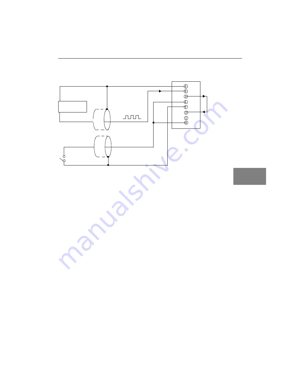
Figure 18: Cascading Counters (Shown for Event Counting Using
Counters 0 and 1 and External Gate 0)
STP300 Panel
TB26
Signal Source
Digital Ground
TB29
TB28
Digital Ground
Gate 0
External
Gating
Switch*
TB27
TB30
User
Counter
Output 0
User Clock
Input 1
TB25
User Clock Input 0
TB32
Gate 1
* An internal 22 k
Ω
pull-up
resistor to +5 V is used.
Summary of Contents for DT300 Series
Page 1: ...R DT300 Series UM 16503 E Getting Started Manual...
Page 6: ...Contents vi...
Page 11: ...1 1 Overview DT300 Series Software 3 Getting Started Procedure 4...
Page 22: ...Chapter 2 12...
Page 44: ...Chapter 4 34...
Page 74: ...Chapter 5 64...
Page 78: ...Chapter 6 68 13 Click Main Menu 14 Click Exit...
Page 86: ...Chapter 6 76...


