background image

V M S   C O M P U T E R   –   A D VA N C E D   F E AT U R E S

14

Sign Status 

This will show the Status of the sign, including:

1.  Serial Number, WW,Y,NN, Week of year, Year letter (A=2017, B=2018 ect), Unit number that was 

manufactured that week

2.  VMS Sign Controller Firmware version xx.xx.xx. (The VMS Computer serial number is displayed 

on start-up)

3.  Message Showing

4.  Battery Voltage i.e. 12.8V

5.  Sign Head Internal Temperature (Celcius)

6.  LDR-F 0000-9999 Front Light sensor, 0000 - is full light level, 9999 is no light level

7.  LDR-R 0000-9999 Rear Light Sensor, 0000 - is full light level, 9999 is no light level

8.  Sign Brightness Level , 1 to 100%, 100% is full brightness.

9.  Tamper condition (OK)

10. Radar (ON) (Enabled)

11. Controller Time  (derived from GPS) – if offset show (+or – HH,MM)

12. GPS Co-ordinates

13. GSM Status  (online) (offline)  SIM fitted

14. GSM Signal strength  xx/31

15. Aux Output Supply (on) (off) (timed)

Summary of Contents for VMS 123

Page 1: ...VMS Computer Advanced Features DataSigns VMS 123 ...

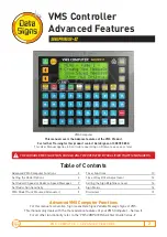
Page 2: ...e features of the VMS Product For further Training for this product contact Data Signs on 1300 785 850 This User Manual applies to Controllers operating on firmware xx xx xx or later Table of Contents THE VARIABLE MESSAGE SIGN SHOULD ONLY BE OPERATED BY QUALIFIED TRAFFIC MANAGERS PTL Controller VMS Computer Advanced VMS Computer Functions For this manual s convention Sign means Data Signs Variable...

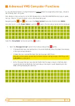
Page 3: ...d a r S e t L o H i M S G V i e w R a d a r S e t u p Select the Setup Radar option and push the button 1 Select the Message Interrupt option in this instance and push the button If Disable Radar was selected then this is the end of the Radar Setup The Radar Functionality of the Sign has been Disabled If Radar Only was selected the Signs Normal message is NOT shown As the Message Interrupt was sel...

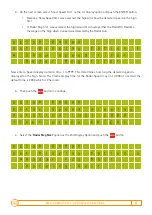
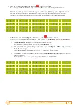
Page 4: ...o n 1 S h o w S p e e d f i r s t R a d a r M s g f i r s t Now enter a Speed display duration time 1 to 9999 This determines how long the detected speed is displayed on the Sign Note The Frame display time for the Radar Speed is set in 1 1000 of a second the default time is 2000 which is 2 Seconds 3 Then push the button to continue S E T U P R A D A R E n t e r S p e e d d i s p l a y d u r a t i...

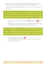
Page 5: ...R 6 On the next screen enter the Speed Limit and push the button to continue Note if for the 2nd display option Nothing Next was chosen the Speed Limit step would be bypassed The Speed Limit is usually set to the current road speed limit For example in a 60 km h speed zone make the Speed Limit 60 If the speed detected by the radar gun is lower or equal to the Speed Limit the Sign will display the ...

Page 6: ...t e r M a x i m u m m S p e e d i n k m h 1 0 0 T h e n p r e s s E N T E R On the next screen select the Yes option to show YOUR SPEED and push the button to continue When this option is set the Sign will display the text YOUR SPEED above the detected speed value Otherwise the detected speed is shown as a larger font size on the sign S E T U P R A D A R S h o w Y O U R S P E E D Y e s N o To send...

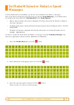
Page 7: ...detected speed is above the Speed Limit i e TOO FAST SLOW DOWN The Radar Lo message is displayed when the detected speed is at or below the Speed Limit i e THANKS DRIVE SAFELY You need to create both the Radar Hi and Radar Lo messages using the Create New Message main menu item Appropriate names would be RADARHI and RADARLO 1 Select the Set Hi Lo Msg option push the button R A D A R O P T I O N S ...

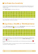
Page 8: ...ive This applies to Signs with RM 32B or Later Version Controllers From the VMS Computer Optns Main Menu select the Status Btn Func sub menu item to change the functionality associated with the button on the VMS COMPUTER B U T T O N F U N C T I O N S t a t u s B L A N K S H O W M S G T M A M o d e Normally the button function is set to display the Sign Status when it is pressed To change the butto...

Page 9: ...ver the SIGN STATUS button to show the operator that this button is now used to enter TMA Mode When in TMA Mode the VMS COMPUTER does not turn off The screen displays the current state of the Sign either running a Message or Blank T M A M O D E S i g n M E S S A G E P r e s s E N T E R T O B L A N K P r e s s M E N U t o e x i t The operator presses the button to blank or re awake the Sign T M A M...

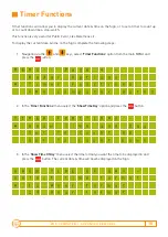
Page 10: ...e main MENU and press the button M E N U P a g e 4 R a d a r O p t i o n s T i m e r F u n c t i o n s V M S C o m p u t e r O p t n s 2 In the Timer Functions menu select the Show Time Day option and press the button T I M E R F U N C T I O N S S h o w T i m e a n d D a y S e t T o C o u n t U p S e t T o C o u n t D o w n 3 In the Show Time Of Day menu select the time format you want the time to...

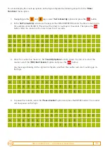
Page 11: ... E T T O C O U N T U P E n t e r e n d t i m e a s H H M M S S T h e n p r e s s E N T E R k e y 3 Once the counter has been set the Count Up Options screen shows To start or re start the counter select the RE Start Counter option and press the button Any message showing on the sign will complete and then the counter will start counting up on the Sign C O U N T U P O P T I O N S R E S T A R T C O ...

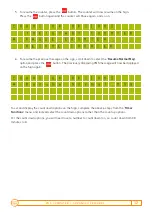
Page 12: ...ge on the sign scroll down to select the Resume Normal Msg option and press the button The previously displaying VMS message will now be displayed on the Sign again C O U N T U P O P T I O N S R e s u m e N o r m a l M S G To set and display the count down options on the Sign complete the above 6 steps from the Timer Functions menu and instead select the count down options rather than the count up...

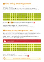
Page 13: ...fitted to the VMS sign controller the correct time will be automatically set This is an Override advanced function for the Brightness level of the output of the LED s on the Sign This level is normally managed automatically by the Sign Controller and will set the Brightness depending on the detected ambient or environmental light conditions and the Signs battery voltage However if you wish to alte...

Page 14: ...wing 4 Battery Voltage i e 12 8V 5 Sign Head Internal Temperature Celcius 6 LDR F 0000 9999 Front Light sensor 0000 is full light level 9999 is no light level 7 LDR R 0000 9999 Rear Light Sensor 0000 is full light level 9999 is no light level 8 Sign Brightness Level 1 to 100 100 is full brightness 9 Tamper condition OK 10 Radar ON Enabled 11 Controller Time derived from GPS if offset show or HH MM...

Page 15: ...s available Notwithstanding the foregoing Data Signs Pty Ltd does not make any warranty as to the information contained herein and does not accept any liability for any injury loss or damage of any kind incurred by use of or reliance upon the information Data Signs Pty Ltd reserves the right to make modifications additions and deletions to this document at any time and without notice The Data Sign...

Reviews: